
Method for Operating an Automation System

a technology of automation system and automation system, applied in the direction of electric programme control, program control, instruments, etc., can solve the problems of delta loading, interruption of control and/or monitoring of the respective technical process, and long time-consuming discussion, and achieve the effect of reducing the impa

Inactive Publication Date: 2011-09-15
SIEMENS AG
View PDF14 Cites 5 Cited by
  • Summary
  • Abstract
  • Description
  • Claims
  • Application Information

AI Technical Summary

Benefits of technology

[0006]It is therefore, an object of the invention to provide a method for operating an automation system in which the aforementioned disadvantages are avoided or at least their impact is reduced.
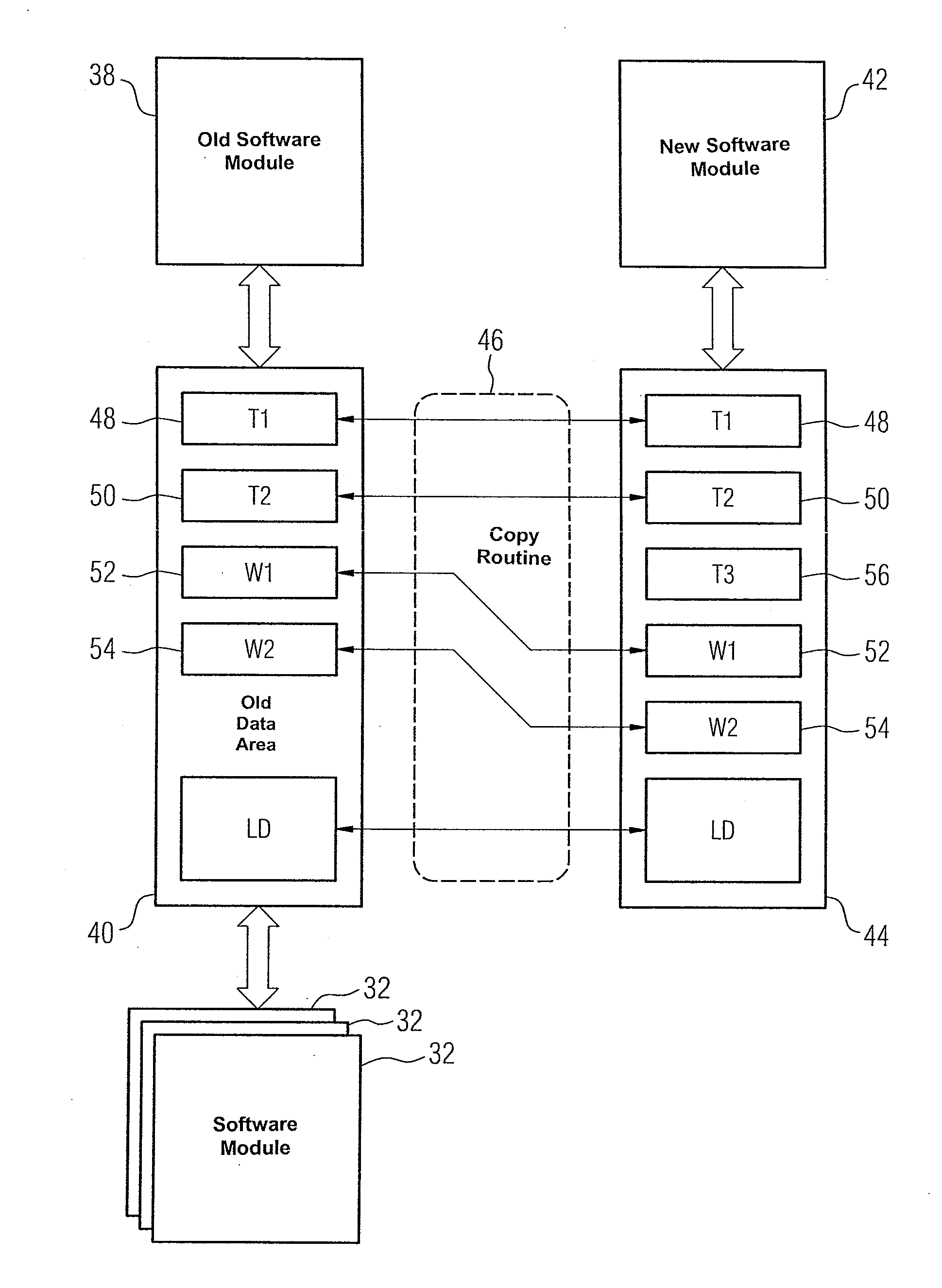
[0011]The approach according to the invention therefore allows one or more software modules in a control program to be replaced without the need to interrupt the control program or other control programs. The control program can therefore be modified at runtime. When reference is made here to other control programs, this means, e.g., a control and monitoring program which is executed as a control program by an automation device provided as a control and monitoring system.
[0016]In an advantageous embodiment, the memory areas occupied by the old software module and / or by the old data area in the memory of the automation system are re-released. This ensures optimal utilization of the memory space available in the automation system and the old software module, which is no longer invoked anyway, and the old data area correlated therewith no longer tie up resources of the automation system unnecessarily.
[0018]In this case, it is particularly preferably that in the event of any program code instructions which relate to the old data area and which cannot automatically be changed into program code instructions relating to the new data area, the substitution of the call for invoking the new program module in place of the old software module in the runtime group module is deferred or prevented until such time as the task list resulting from such program code instructions has been emptied. It is achieved in this way that it will only be possible to invoke the new software module when its provision and disposal is fully ensured through corresponding copying over from the old data area into the new data area and vice versa, with the result that the functional integrity of the control program as a whole is guaranteed.
[0019]In a method for operating an automation system, as described here and in the following, when a plurality of new software modules are substituted for a corresponding plurality of old software modules a new software module from the plurality of the new software modules is preferably substituted in succession for each corresponding old software module and a replacement sequence within the plurality of new software modules is chosen in accordance with a respective call hierarchy for invocation of the respective old or new software module. This takes into account, on the one hand, that it is not possible to replace an arbitrarily large number of software modules simultaneously. On the other hand, the replacement process in accordance with the call hierarchy occurs according to a clear structure which, e.g., also simplifies the manual processing of a task list, because all the entries present in the task list relate to one and the same software module.

Problems solved by technology

The problems associated with delta loading have been the subject of discussion for a long time.
In an automation system that is in the stopped state there is consequently also an interruption to the control and / or monitoring of the respective technical process for the duration of the stopped state.

Method used


Image

  • Method for Operating an Automation System
  • Method for Operating an Automation System
  • Method for Operating an Automation System

Examples


Embodiment Construction

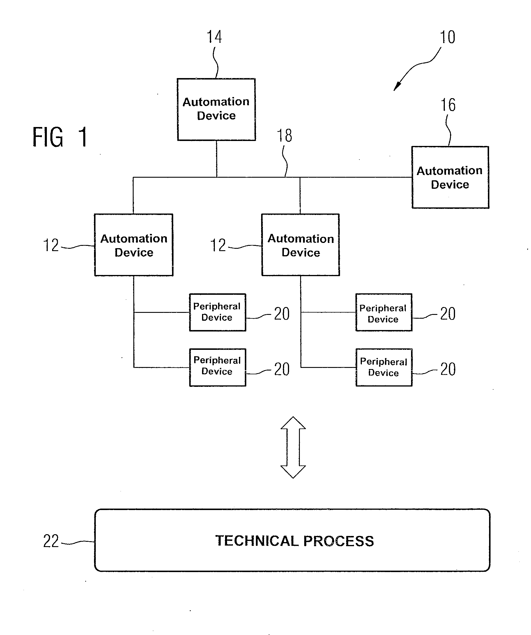
[0034]FIG. 1 shows an exemplary embodiment of an automation system 10, which comprises at least one automation device 12, a plurality of automation devices 12, 14, 16. In this embodiment, the automation device 14 is a control station or engineering system 14 and the automation device 16 an operator control and monitoring device 16. The automation devices 12, 14, 16 are communicatively connected to one another, e.g., over a bus 18. Overall, they are intended together with any decentralized peripheral devices 20 for controlling and / or monitoring a technical process 22 (not shown in greater detail), possibly without a temporarily connected control station serving as an engineering system.

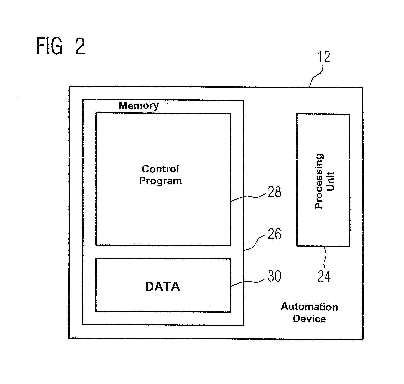
[0035]FIG. 2 shows in schematically simplified form, taking one of the automation devices 12, 14, 16 from FIG. 1 as an example, that each device includes a processing unit 24 comprising a processor or the like and a memory 26. A control program 28, which specifies how the respective automation device 1...


PUM


Abstract

A method for operating an automation system which executes, as an automation solution, a control program having a plurality of software modules, where the method comprises replacing at least one software module comprising an old software module at the runtime of the control program with a new software module wherein the new software module is loaded into a memory of the automation system, an old data area associated with the old software module is compared with a new data area associated with the new software module, program code instructions for converting data for or from the old data area into data for or from the new data area is generated, and a program code instruction for invoking the old software module is replaced with program code instructions for invoking the generated program code instructions for data conversion and for invoking the new software module.

Description

BACKGROUND OF THE INVENTION[0001]1. Field of the Invention[0002]The invention relates to a method for operating an automation system having a memory in which a control program is stored as an automation solution and, more specifically, to a situation such as arises when at the runtime of parts of the control program these parts of the control program have to be replaced with updated parts without the execution of the control program and overall operation of the automation system being noticeably interrupted. Such a replacement of parts of the control program is referred to as delta loading, where such parts of the control program are referred to in the following as software modules.[0003]2. Description of the Related Art[0004]The problems associated with delta loading have been the subject of discussion for a long time. At present, however, only solutions that can be used if no change is made to the interface of the respective software modules are available for automation systems. T...

Claims


Application Information

Patent Timeline
Patent Type & Authority Applications(United States)
IPC IPC(8): G05B19/42
CPCG06F8/67G06F8/656
Inventor GRAF, MARKUS
Owner SIEMENS AG
Learn More