Telescoping mounting system for a recessed luminaire

a technology for recessed luminaires and mounting systems, which is applied in the field of mounting systems, can solve the problems of unnecessarily increasing tooling expenditure, components cost and inventory handling, and reducing profits and operations efficiency, and achieves the effects of facilitating engagement, improving installation and adjustment, and eliminating scrap materials

Active Publication Date: 2011-09-22
ABL IP HLDG
View PDF7 Cites 78 Cited by
  • Summary
  • Abstract
  • Description
  • Claims
  • Application Information

AI Technical Summary

Benefits of technology

[0010]In an implementation of the present invention, a telescoping mounting system improves installation and adjustment between a recessed luminaire and a framing structure. The mounting system includes two telescoping bars having a generally identical S-shaped cross-sectional profile. The S-shaped profile allows both telescoping bars to function as either the “male” membe

Problems solved by technology

As such, having to manufacture and install two separate components (i.e., members) for the telescoping assemblies unnecessarily increases tooling expenditure, components cost, and inventory handling.
Thus, usage of present telescoping assemblies results in decreased profits and operations efficiency.
Another problem with typical telescoping bars is that they tend to have cross-sectional shapes of low strength and rigidity.
In addition, typical telescoping bars are manufactured using processes that result in scrap material, resulting in material waste and increased manufacturing costs.
However, the free-sliding components have the potential to cause binding, damage, and/or injury during the handling, i

Method used


Image

  • Telescoping mounting system for a recessed luminaire
  • Telescoping mounting system for a recessed luminaire
  • Telescoping mounting system for a recessed luminaire

Examples


Embodiment Construction

[0035]Although the invention will be described in connection with certain preferred embodiments, it will be understood that the invention is not limited to those particular embodiments. On the contrary, the invention is intended to include all alternatives, modifications and equivalent arrangements as may be included within the spirit and scope of the invention as defined by the appended claims.

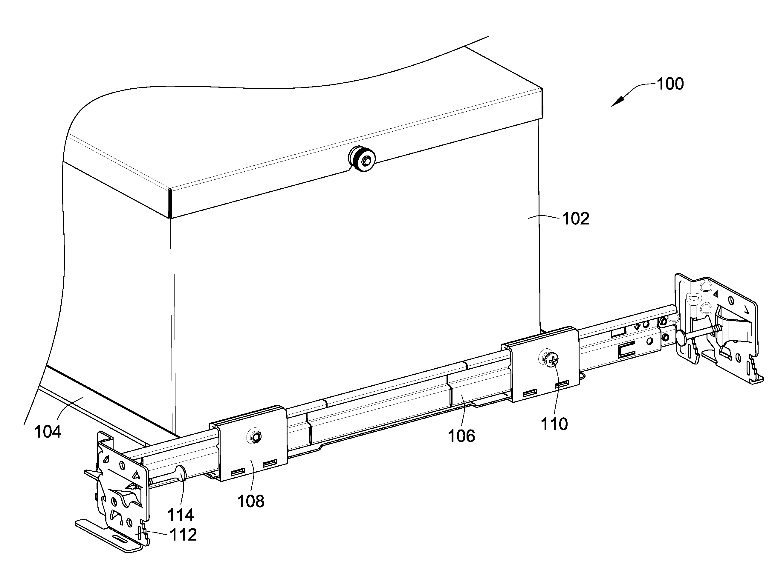
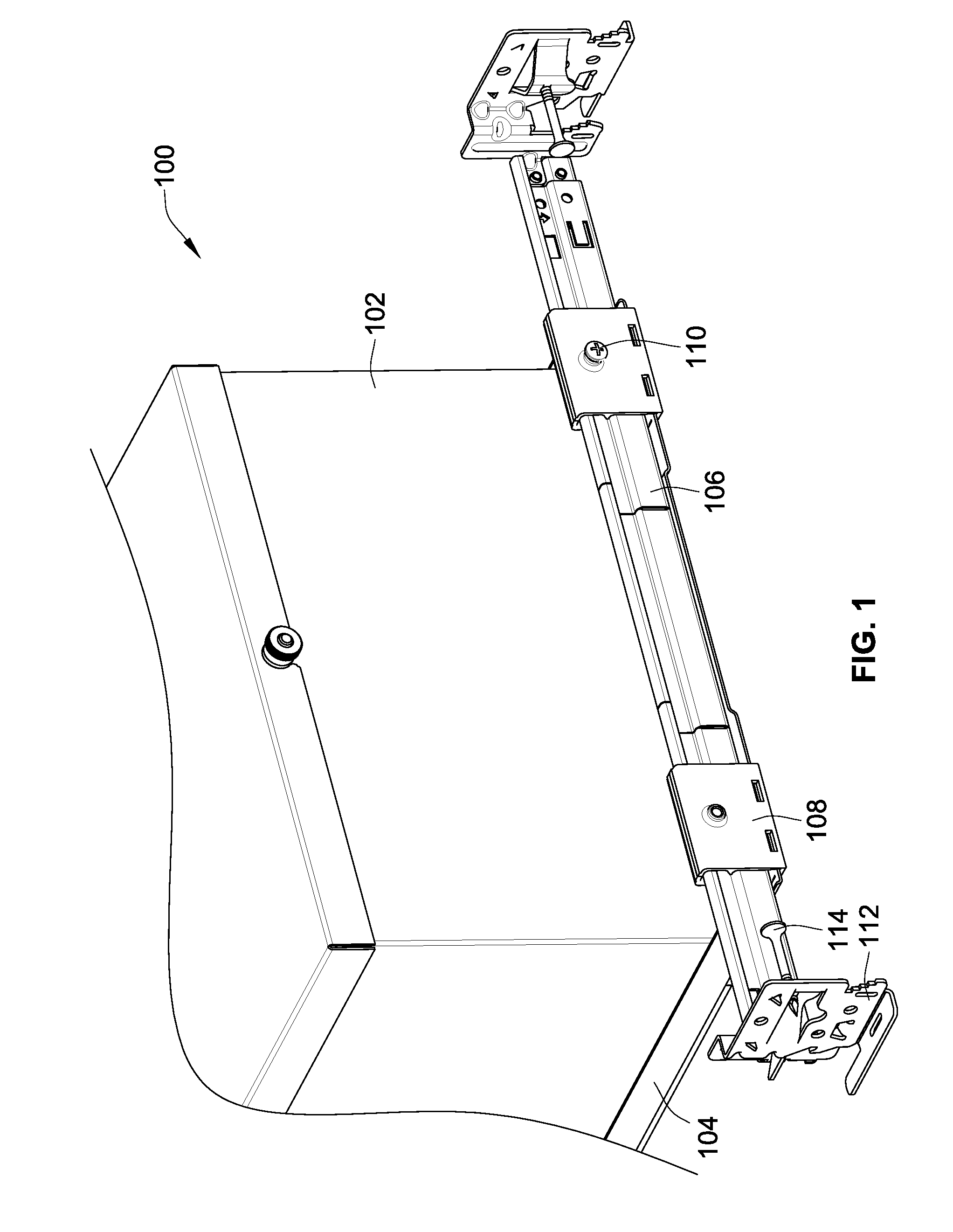
[0036]Referring to FIG. 1, a recessed fixture in the form of a recessed luminaire 100 includes a luminaire housing 102 and a mounting assembly including a plaster frame 104 and a pair of telescoping bars 106. In other embodiments the recessed fixture can also be, for example, an audio speaker, an electrical fan, or an electrical box.

[0037]The telescoping bars 106 are attached to the plaster frame 104 using a pair of mounting guides 108. A locking screw 110 is used, generally, as a set screw to prevent motion of the bars 106 relative to the mounting guide 108. The telescoping bars 106 are rigi...


PUM


Abstract

A lighting assembly for a recessed luminaire includes a plaster frame for supporting the recessed luminaire and a pair of telescoping bars for attaching the plaster frame to framing support members. The telescoping bars include a first bar and a second bar, each of the bars having a generally S-shaped cross-sectional profile that is defined by a center curve joining a first area and a second area, which are generally hook-shaped and extend perpendicularly from the center curve in opposing directions. The first area of the first bar is overlappingly positioned at least in part within the second area of the second bar, and the first area of the second bar is overlappingly positioned at least in part within the second area of the second bar whereby the first and second bars are mated in an inverted and opposed adjacent relationship allowing sliding extension of the bars.

Description

FIELD OF THE INVENTION[0001]This invention is directed generally to mountings systems, and, more particularly, to a telescoping system for mounting a recessed luminaire to a building structure.BACKGROUND OF THE INVENTION[0002]Typically, prior to installation of a finished ceiling, a recessed luminaire (also referred to as a light fixture) is secured to wood and / or steel framing of a building using telescoping bars that cover common spacing between parallel framing members. For example, the telescoping bars cover a joist spacing in the range of about 16 inches-24 inches or a T-bar spacing in the range of about 24 inches.[0003]After attachment to the building framing, the recessed luminaire can be adjusted perpendicular to the framing members by sliding it along the telescoping bars. The telescoping bars generally require two distinct members—a male member and a female member—to form a telescoping assembly. As such, having to manufacture and install two separate components (i.e., memb...

Claims


Application Information

Patent Timeline
IPC IPC(8): F16M13/02
CPCF21S8/026Y10S248/906F21V21/048
Inventor FRYZEK, AARON P.COLLINS, KERRY
Owner ABL IP HLDG
Why Eureka
Try Eureka