Vertical pillar structured photovoltaic devices with mirrors and optical claddings

a photovoltaic device and vertical pillar technology, applied in the manufacture of final products, discharge tubes/lamp details, instruments, etc., can solve the problems of not having a drawback for photovoltaic devices, unable to contribute to electricity generation,

Inactive Publication Date: 2011-09-22
ZENA TECH
View PDF108 Cites 68 Cited by
  • Summary
  • Abstract
  • Description
  • Claims
  • Application Information

AI Technical Summary

Benefits of technology

[0006]Described herein is a photovoltaic device operable to convert light to electricity, comprising a substrate, a plurality of structures essentially perpendicular to the substrate, one or more recesses between the structures, each recess having a sidewall and a bottom wall, and a planar reflective layer disposed on the bottom wall of each recess, wherein the structures are a single crystalline semiconductor material and wherein the sidewall of each recess is free of the planar reflective layer. Unlike a conventional solar cell, light incident on the planar reflective layer is not wasted but reflected to the structures to be absorbed and converted to electricity. This photovoltaic device can also be used as a photo detector.

Problems solved by technology

Any light incident on such opaque electrodes is either reflected away from the solar cell or absorbed by the opaque electrodes, and thus does not contribute to generation of electricity.
Therefore, a photovoltaic device that does not have this drawback is desired.

Method used


Image

  • Vertical pillar structured photovoltaic devices with mirrors and optical claddings
  • Vertical pillar structured photovoltaic devices with mirrors and optical claddings
  • Vertical pillar structured photovoltaic devices with mirrors and optical claddings

Examples


examples

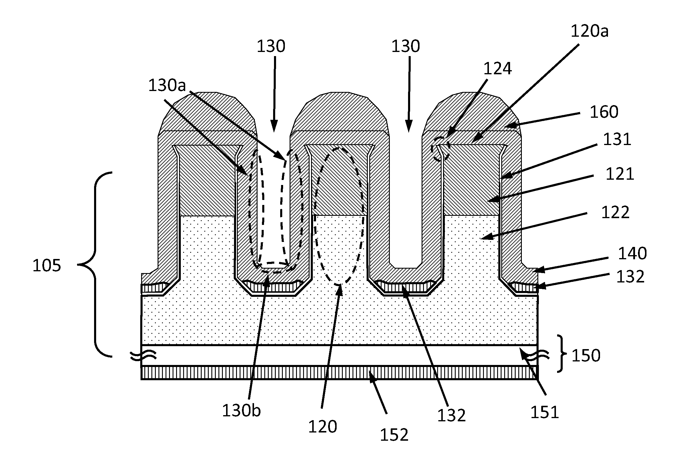
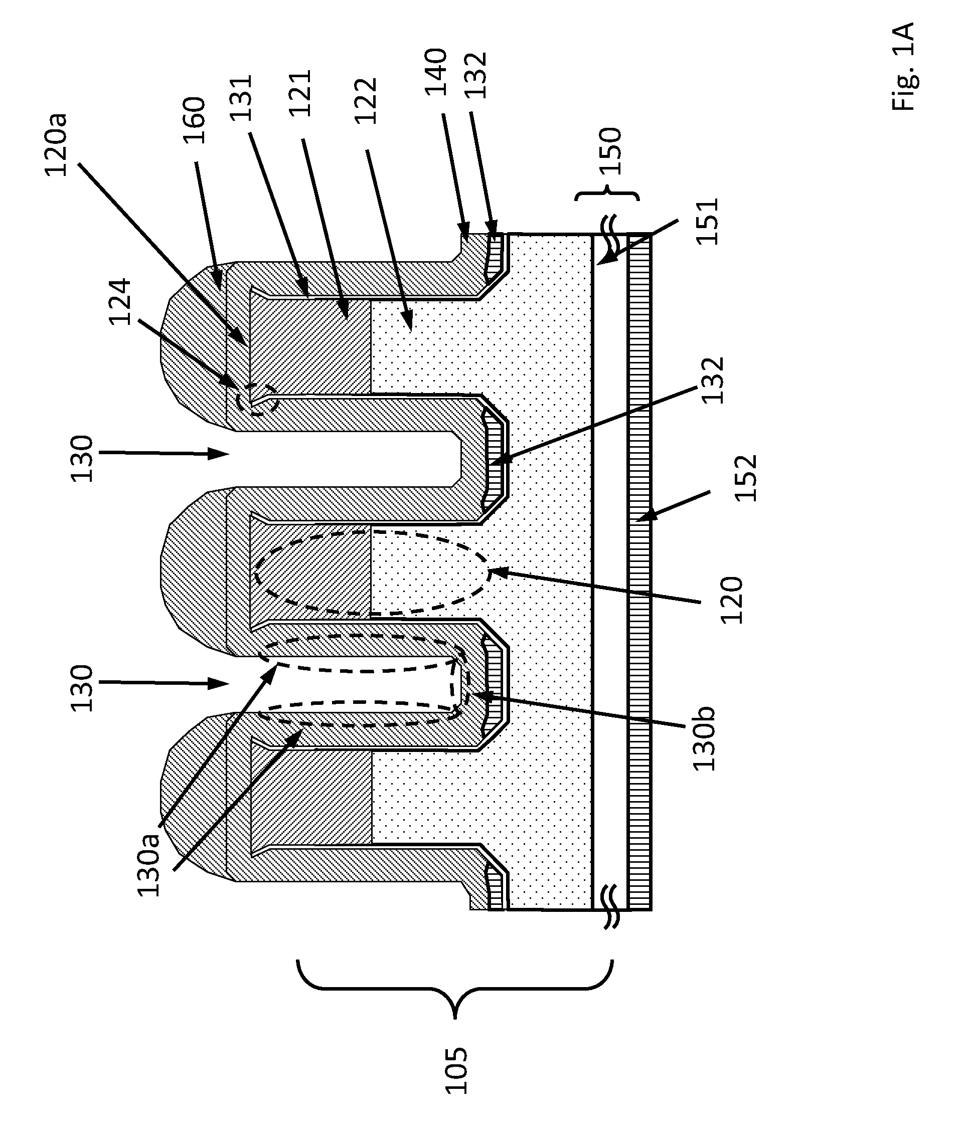
[0054]FIG. 1A shows a schematic cross-section of a photovoltaic device 100, according to an embodiment. The photovoltaic device 100 comprises a substrate 105, a plurality of structures 120 essentially perpendicular to the substrate 105 and one or more recesses 130 between the structures 120. Each recess 130 has a sidewall 130a and a bottom wall 130b. The sidewall 130a and the bottom wall 130b both have a passivation layer 131. A top surface 120a of the structures 120 is free of the passivation layer 131. The bottom wall 130b has a planar reflective layer 132 disposed on the passivation layer 131. The sidewall 130a does not have any planar reflective layer. Each structure 120 has a top portion 121 and a bottom portion 122, the top portion 121 and the bottom portion 122 having dissimilar conduction types. The term “dissimilar conduction types” as used herein means that the top portion 121 and the bottom portion 122 cannot be both p type, or both n type. The structures 120 can have one...


PUM


Abstract

A photovoltaic device operable to convert light to electricity, comprising a substrate, a plurality of structures essentially perpendicular to the substrate, one or more recesses between the structures, each recess having a planar mirror on a bottom wall thereof. The structures have p-n or p-i-n junctions for converting light into electricity. The planar mirrors function as an electrode and can reflect light incident thereon back to the structures to be converted into electricity.

Description

CROSS-REFERENCE TO RELATED APPLICATIONS[0001]This application is related to U.S. patent application Ser. Nos. 12 / 204,686 (granted as U.S. Pat. No. 7,646,943), 12 / 648,942, 12 / 270,233, 12 / 472,264, 12 / 472,271, 12 / 478,598, 12 / 573,582, 12 / 575,221, 12 / 633,323, 12 / 633,318, 12 / 633,313, 12 / 633,305, 12 / 621,497, 12 / 633,297, 61 / 266,064, 61 / 357,429, 61 / 306,421, 61 / 306,421 and 12 / 910,664, the disclosures of which are hereby incorporated by reference in their entirety.BACKGROUND OF THE INVENTION[0002]A photovoltaic device, also called a solar cell is a solid state device that converts the energy of sunlight directly into electricity by the photovoltaic effect. Assemblies of cells are used to make solar modules, also known as solar panels. The energy generated from these solar modules, referred to as solar power, is an example of solar energy.[0003]The photovoltaic effect is the creation of a voltage (or a corresponding electric current) in a material upon exposure to light. Though the photovoltaic...

Claims


Application Information

Patent Timeline
Patent Type & Authority Applications(United States)
IPC IPC(8): H01L31/0232H01L31/18H01J40/14
CPCH01L31/03529H01L31/068H01L31/075H01L31/103H01L31/056H01L31/1804Y02E10/52Y02E10/548Y02E10/547H01L31/105Y02P70/50H01L31/04H01L31/18
Inventor YU, YOUNG-JUNEWOBER, MUNIB
Owner ZENA TECH
Why Eureka
Try Eureka