Seismic isolation device and seismic isolation structure

a seismic isolation and device technology, applied in the direction of shock absorbers, machine supports, mechanical apparatus, etc., can solve the problems of increased cost, difficulty in material selection, and inaction of the seismic isolation mechanism, so as to reduce acceleration, prevent damage to displayed objects standing on the upper structure or the like, and reduce the effect of acceleration

Inactive Publication Date: 2011-09-22
TOKYO DENKI UNIVERSITY
View PDF5 Cites 15 Cited by
  • Summary
  • Abstract
  • Description
  • Claims
  • Application Information

AI Technical Summary

Benefits of technology

[0030]Further, the present invention relates to a seismic isolation structure, and the structure is characterized by comprising at least three seismic isolation devices described above. With this invention, destruction of an upper structure, damage of a displayed object standing on the upper structure or the like can preferably be prevented.
[0031]As des...

Problems solved by technology

As a result, when a small frictional force or a large frictional force is required, the material of the sliding face should be changed, and in case that the material of the sliding face is changed, it is necessary to sufficiently consider generation of an excess resistance force caused by static frictional coefficient that may be generated at the start of a slide, which provides difficulty in selection of the material.
On the other hand, in the seismic isolation devices described in Patent documents 2, 3, although large effect is expected in that vibration caused by an earthquake is isolated, in order to effectively use air pressure, accurate sealing ...

Method used


Image

  • Seismic isolation device and seismic isolation structure
  • Seismic isolation device and seismic isolation structure
  • Seismic isolation device and seismic isolation structure

Examples


first embodiment

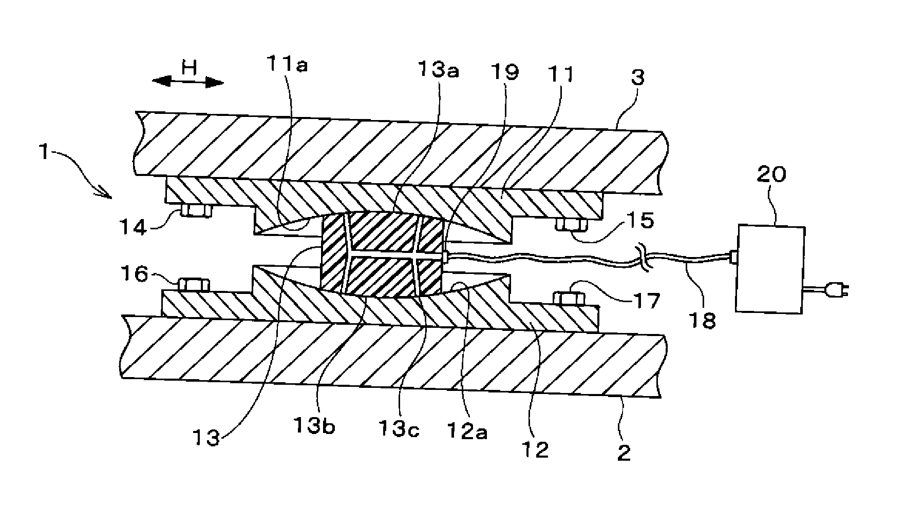
[0041]FIG. 1 shows a seismic isolation device according to the present invention, this seismic isolation device 1 is mounted between a lower structure 2 such as a foundation of a detached house and an upper structure 3, such as a detached house, which is movable in a horizontal direction H in relation to the lower structure 2 through the seismic isolation device 1.

[0042]The seismic isolation device 1 is provided with an upper plate 11 that is fixed to the upper structure 3 and has a spherically concave lower surface 11a with a downward opening; a lower plate 12 that is fixed to the lower structure 2 and has a spherically concave upper surface 12a with an upward opening; and a movable body 13 that is movably arranged between the upper plate 11 and the lower plate 12. The upper plate 11 is fixed to the upper structure 3 with the bolts 14, 15, and the lower plate 12 is fixed to the lower structure 2 with the bolts 16, 17.

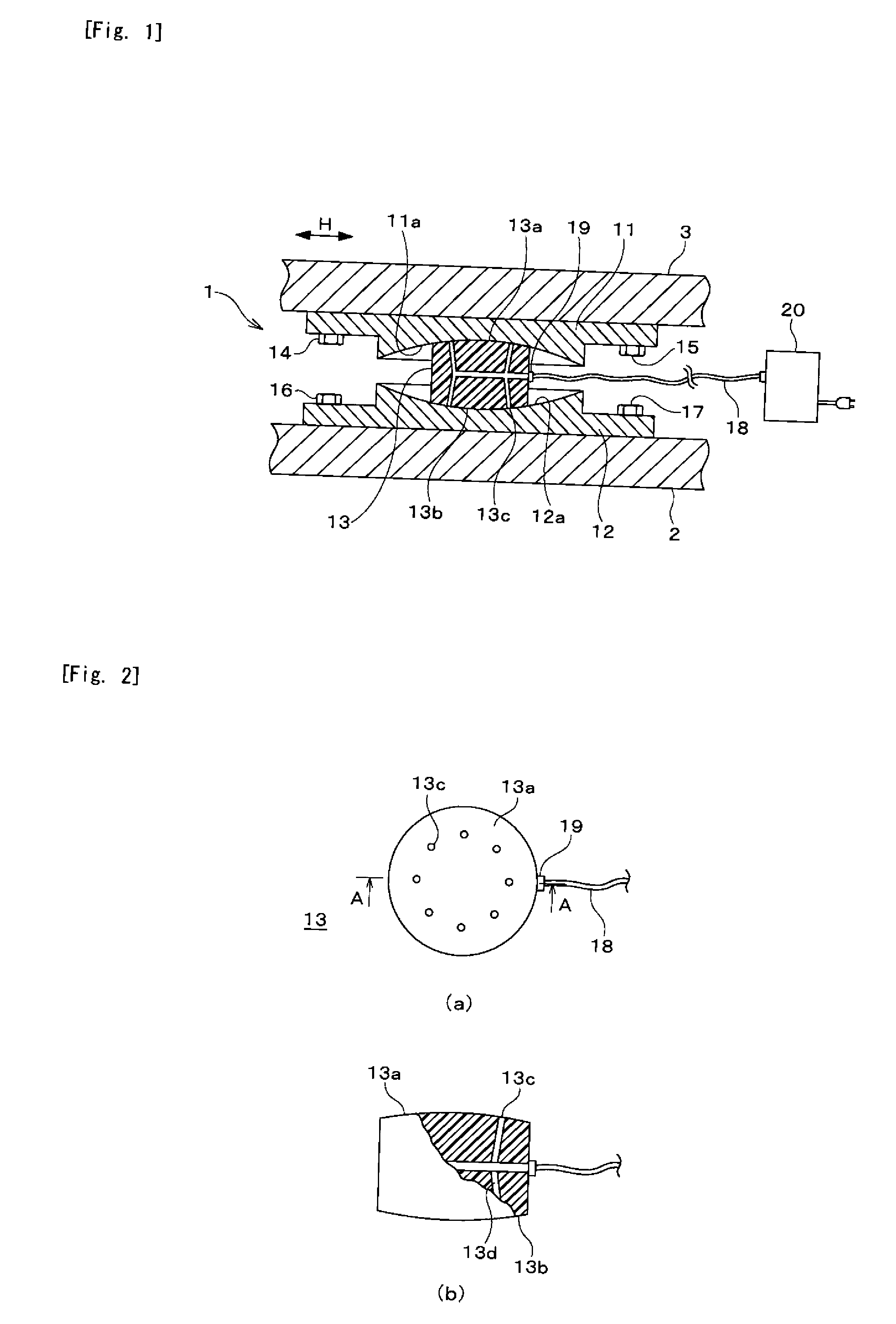
[0043]The movable body 13 is provided with a spherically convex u...

second embodiment

[0058]Next, a seismic isolation device according to the present invention will be explained with reference to FIG. 7. This seismic isolation device 41 is also mounted between a lower structure 42 such as a foundation of a detached house and an upper structure 43, such as a detached house, which is movable in a horizontal direction H in relation to the lower structure 42 via the seismic isolation device 41.

[0059]The seismic isolation device 41 is provided with an upper plate 51 that is fixed to the upper structure 43; a lower plate 52 that is fixed to the lower structure 42 and has a spherically concave upper surface 52a with an upward opening; a movable body 53 that is movably arranged between the upper plate 51 and the lower plate 52; and a pillar-shaped connection part 44 arranged between the movable body 53 and the upper plate 51, in which a spherical member 44a of the pillar-shaped connection part 44 is pivoted on the upper plate 51 through retaining members 45, 46, and a lower ...


PUM


Abstract

The present invention is intended to provide a seismic isolation device which, regardless of a load to be supported, is capable of reducing acceleration through lengthening a natural period of an upper structure, with excellent vibration energy absorbing capacity by obtaining a properly preferable frictional force as well as a returning characteristic, and others.

Description

CROSS-REFERENCE TO RELATED APPLICATIONS[0001]The present application claims priority to International Application No. PCT / JP2008 / 068949 filed on Oct. 20, 2008, which claims priority to Japanese Patent Application No. 2007-274907 filed on Oct. 23, 2007.STATEMENT RE: FEDERALLY SPONSORED RESEARCH / DEVELOPMENT[0002]Not ApplicableBACKGROUND OF THE INVENTION[0003]1. Technical Field of the Invention[0004]The present invention relates to a seismic isolation device for light weight structures, such as detached houses, equipments and display stands, and a seismic isolation structure with the seismic isolation device, and more particularly to a seismic isolation device, which is disposed between an upper structure such as a building and a lower structure like a foundation, for reducing transmission of a vibration of the lower structure caused by earthquake, traffic or others to the upper structure and for preventing, for instance, collapse of the upper structure or damage of displayed objects m...

Claims


Application Information

Patent Timeline
IPC IPC(8): F16F15/027
CPCE04H9/023E04B1/985E04H2009/026F16F15/027E04H9/0235E04H9/0215
Inventor FUJITA, SATOSHITANAKA, GOMIYAZAKI, MITSURUOZAWA, HIDEO
Owner TOKYO DENKI UNIVERSITY
Why Eureka
Try Eureka