Laser driving unit and image forming apparatus

a laser driving unit and laser technology, applied in the direction of electrographic process, electrographic process apparatus, instruments, etc., can solve the problems of banding noise in a background portion, the pulse width of the light emitted from the semiconductor laser may not be made wide to an extent desired, and the delay generated in the light emission of the semiconductor laser

Active Publication Date: 2011-09-22
RICOH KK
View PDF29 Cites 51 Cited by
  • Summary
  • Abstract
  • Description
  • Claims
  • Application Information

AI Technical Summary

Benefits of technology

[0021]Another and more specific object in one embodiment of the present invention is to provide a laser driving unit and an image forming apparatus, that may correct a driving current depending on a light emission state of a light source.

Problems solved by technology

As a result, delay is generated in the light emission from the semiconductor laser.
However, when the semiconductor laser is to be driven at a high speed in order to realize high-speed operation in equipments such as laser printers, optical disk drives, and digital copying apparatuses, for example, a pulse width of the light that is emitted from the semiconductor laser may not be made wide to an extent desired.
In addition, when the semiconductor laser driven by the biased type is used in an image forming apparatus such as the laser printer and the digital copying apparatus, for example, a banding type noise may appear in a background portion of the paper that is subjected to the printing or copying.
Further, when a low tone is to be reproduced on the paper by the image forming apparatus using the light having a narrow pulse width on the order of several ns (nano-seconds) or less, for example, the output of the semiconductor laser may not reach its peak intensity.
Consequently, the low tone that is actually reproduced may become lower than originally intended, and a correct tone reproduction may be difficult to achieve.
However; this proposed technique cannot control a peak of the differential pulse, and the semiconductor laser may break down.
In addition, because the time in which the differential pulse is superimposed on the driving current is dependent on a differential waveform, the tone of the low tone region may only be improved at an initial stage of the correction, and the gradation representation may not increase linearly after the initial stage of the correction.
Hence, a high-speed response of the optical waveform may not be obtained from the semiconductor laser and the response of the optical waveform may be slow, depending on the structure of the driving circuit, the circuit board, and the like.
As a result, when the semiconductor laser is used in the image forming apparatus, for example, these differences may cause inconsistencies in the tone reproduction, color registration error, and the like.

Method used


Image

  • Laser driving unit and image forming apparatus
  • Laser driving unit and image forming apparatus
  • Laser driving unit and image forming apparatus

Examples


Embodiment Construction

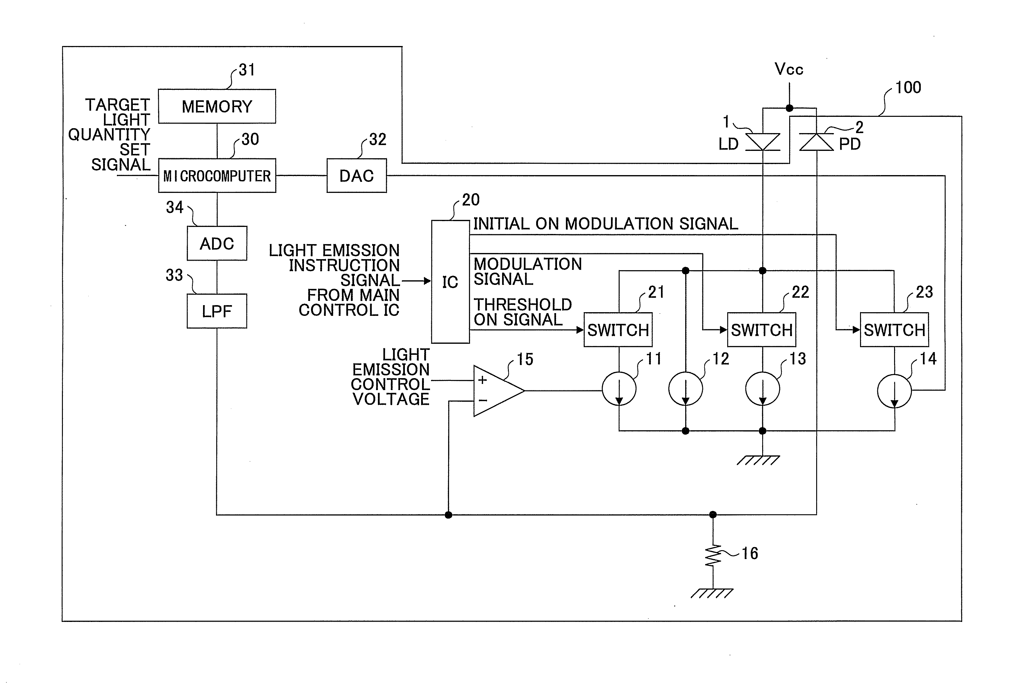
[0048]A description will be given of embodiments of a laser driving unit and an image forming apparatus according to the present invention, by referring to the drawings. The laser driving unit may be used in various apparatuses that include laser light sources. Examples of such apparatuses include a laser printer, an optical disk drive, a digital copying apparatus, and an optical communication apparatus. The digital copying apparatus may include the so-called MFP (Multi-Function Peripheral).

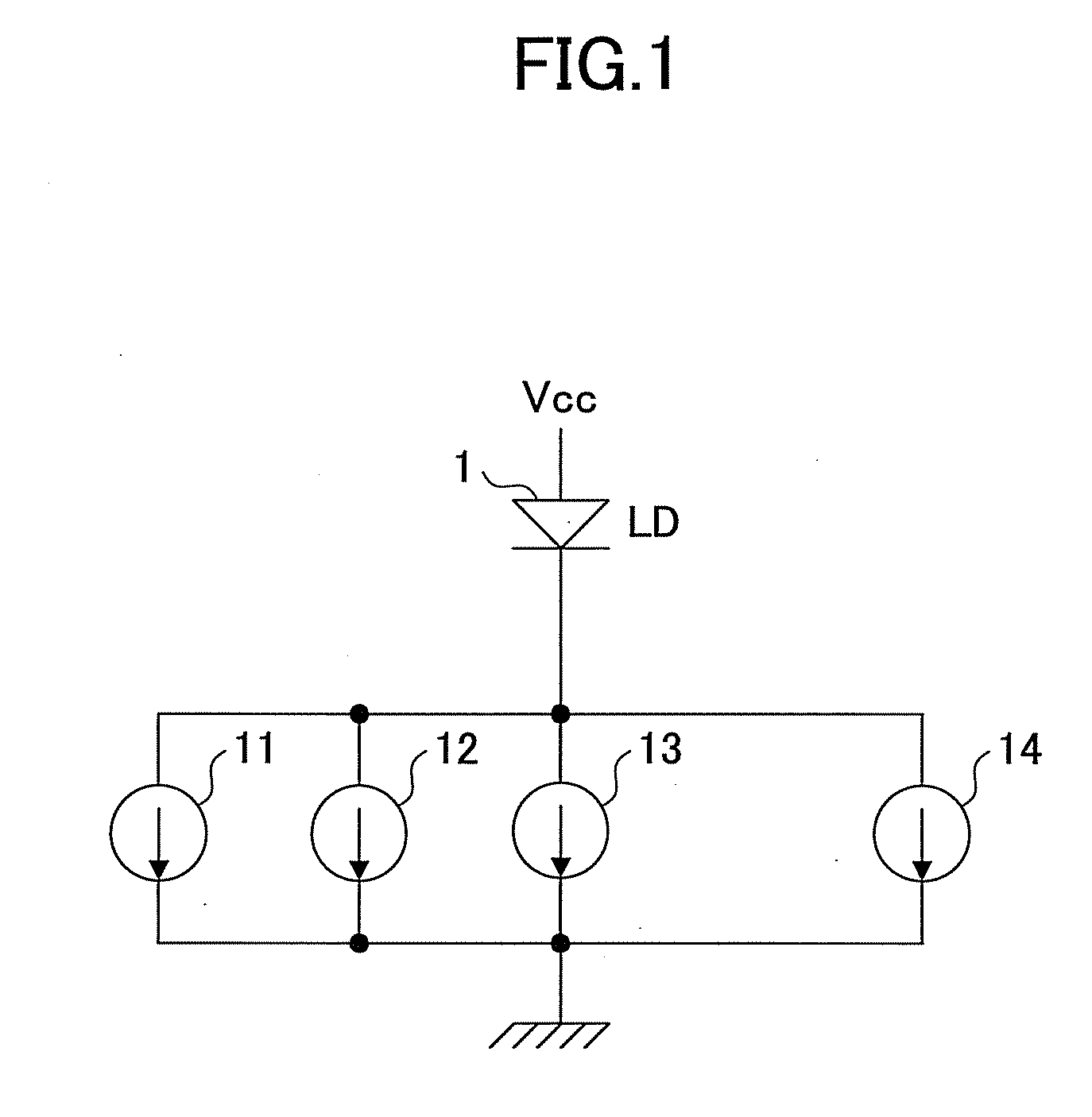
[0049]FIG. 1 is a circuit diagram for explaining a semiconductor laser in an embodiment of the present invention. As illustrated in FIG. 1, a semiconductor laser driving unit includes four current sources to drive a semiconductor laser (hereinafter referred to as a LD (Laser Diode) 1. The four current sources include a threshold current source 11, a bias current source 12, a modulation current source 13, and an initial ON modulation current source 14.

[0050]A bias current output from the bias curr...


PUM


Abstract

A laser driving unit drives a semiconductor laser apparatus including a plurality of light sources, includes a light detecting part to detect light emissions from the light sources, a driving current generator to generate a driving current based on an input signal, an auxiliary driving current generator to generate an auxiliary driving current in an initial time period of an ON-time of the driving current, and an auxiliary current set part to set an auxiliary amount of the auxiliary driving current to be added to the driving current, for each of the light sources, based on a difference between the light emissions detected by the light detecting part and a target light emission of the light sources.

Description

CROSS-REFERENCE TO RELATED APPLICATIONS[0001]This application claims the benefit of Japanese Patent Applications No. 2010-58716 filed on Mar. 16, 2010 and No. 2010-234877 filed on Oct. 19, 2010, in the Japanese Patent Office, the disclosure of which is hereby incorporated by reference.BACKGROUND OF THE INVENTION[0002]1. Field of the Invention[0003]The present invention generally relates to a laser driving unit and an image forming apparatus that includes such a laser driving unit.[0004]2. Description of the Related Art[0005]Conventional semiconductor laser driving circuits may be roughly categorized into a zero-biased (or non-biased) type and a biased type. The zero-biased type semiconductor laser driving circuit sets a bias current of a semiconductor laser to zero, and drives the semiconductor laser by a pulse current corresponding to an input signal. Examples of the zero-biased type semiconductor laser driving circuit are proposed in Japanese Laid-Open Patent Publications No. 4-28...

Claims


Application Information

Patent Timeline
Patent Type & Authority Applications(United States)
IPC IPC(8): B41J2/435H01S3/00
CPCG03G15/043G03G2215/0404G03G15/04072B41J2/473B41J2/455
Inventor OMORI, ATSUFUMIISHIDA, MASAAKI
Owner RICOH KK
Why Eureka
Try Eureka