
Suspension assembly having a microactuator electrically connected to a gold coating on a stainless steel surface

a suspension assembly and micro-actuator technology, applied in the direction of maintaining the alignment of the head carrier, recording information storage, instruments, etc., can solve the problems of oxidation layer on the stainless steel surface, affecting the rotational speed of the disk, and affecting the stability of the suspension assembly

Active Publication Date: 2011-09-22
WESTERN DIGITAL TECH INC
View PDF23 Cites 65 Cited by
  • Summary
  • Abstract
  • Description
  • Claims
  • Application Information

AI Technical Summary

Benefits of technology

The patent describes a new suspension assembly for a device. It includes a mounting plate, a structure for mounting a microactuator, a load beam, and a flexible laminated piece that connects to the load beam. The flexible piece has a surface that can hold a read head. The assembly also has a stainless steel surface with a gold coating and the microactuator is connected to the gold coating. The technical effect of this design is to provide a reliable and efficient connection between the microactuator and the read head, which can improve the performance and reliability of the device.

Problems solved by technology

Also, disk drive performance requirements, especially requirements pertaining to the time required to access desired data, have not allowed the rotational speed of the disk to be reduced.
However, if the microactuator is electrically connected to a stainless steel surface of the suspension assembly (e.g. for grounding), an electrochemical reaction may cause an oxidation layer to form on the stainless steel at the connection location.
The oxidation layer may be insulative and interfere with desired electrical conduction, and may be exacerbated by hot and humid conditions.
Over time, the desired response of the microactuator to applied signals may become diminished, leading to reduced or impaired performance of the information storage device and / or data loss.

Method used


Image

  • Suspension assembly having a microactuator electrically connected to a gold coating on a stainless steel surface
  • Suspension assembly having a microactuator electrically connected to a gold coating on a stainless steel surface
  • Suspension assembly having a microactuator electrically connected to a gold coating on a stainless steel surface

Examples


Embodiment Construction

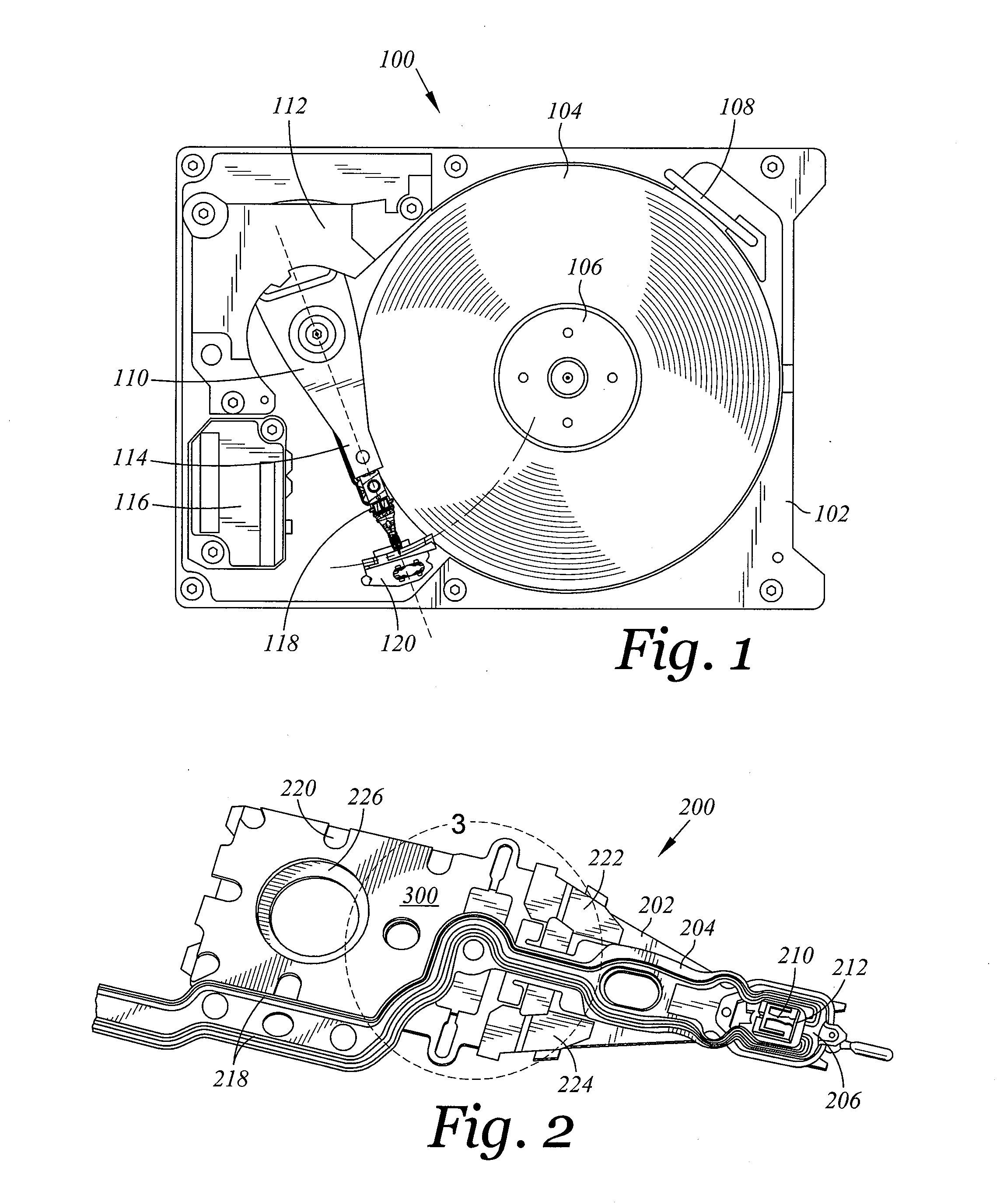
[0022]FIG. 1 is top view of a disk drive 100 that is capable of including an embodiment of the present invention. The disk drive 100 includes a disk drive base 102. The disk drive 100 further includes a spindle 106, rotably mounted on the disk drive base 102, for rotating a disk 104 that is mounted on the spindle 106. The rotation of the disks 104 establishes air flow through optional recirculation filter 108. In certain embodiments, disk drive 100 may have only a single disk 104, or alternatively, two or more disks.

[0023]The disk drive 100 further includes a rotary coarse actuator 110 that is rotably mounted on disk drive base 102. The rotary coarse actuator 110 includes an actuator arm 114 that supports a head gimbal assembly (HGA) 118. Voice coil motor 112 rotates the actuator 110 through a limited angular range so that the HGA 118 may be desirably positioned relative to one or more tracks of information on the disk 104. Preferably the disk drive 100 will include one HGA 118 per ...


PUM

PropertyMeasurementUnit
conductiveaaaaaaaaaa
electrically conductiveaaaaaaaaaa
torqueaaaaaaaaaa

Abstract

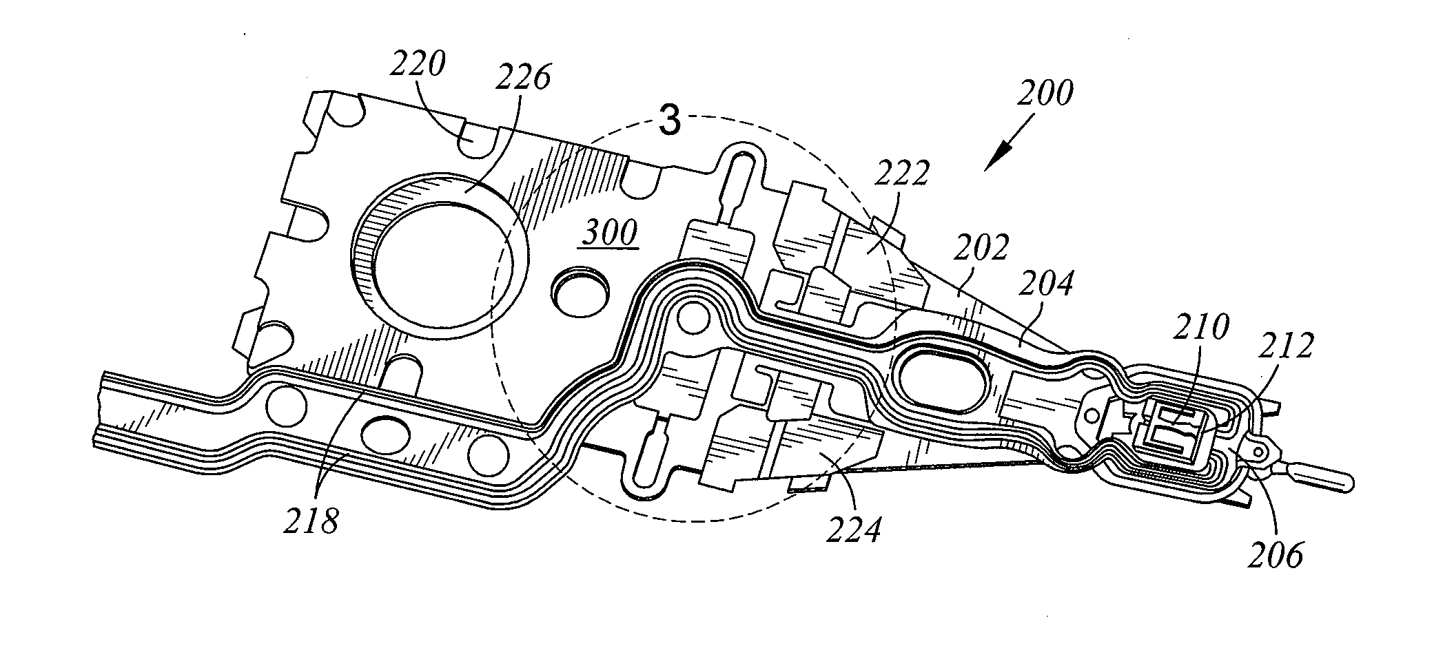
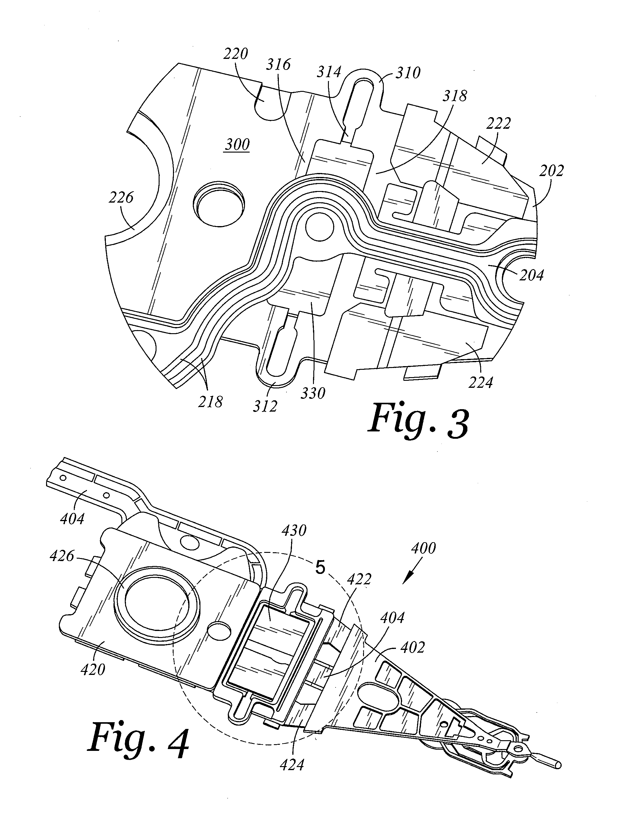
A novel suspension assembly includes a suspension assembly mounting plate, a microactuator mounting structure extending from the suspension assembly mounting plate, a load beam extending from the microactuator mounting structure, and a laminated flexure attached to the load beam. The laminated flexure includes a tongue that has a read head bonding surface. The suspension assembly includes a stainless steel surface having a gold coating, and a piezoelectric microactuator attached to the microactuator mounting structure and electrically connected to the gold coating.

Description

BACKGROUND OF THE INVENTION[0001]1. Field of the Invention[0002]The present invention relates generally to the field of information storage devices, and more particularly to microactuators and suspension assemblies that are used to position read heads in information storage devices.[0003]2. Background of the Art[0004]Information storage devices are used to retrieve and / or store data in computers and other consumer electronics devices. A magnetic hard disk drive is an example of an information storage device that includes one or more heads that can both read and write, but other information storage devices also include heads—sometimes including heads that cannot write. For convenience, all heads that can read are referred to as “read heads” herein, regardless of other devices and functions the read head may also perform (e.g. writing, flying height control, touch down detection, lapping control, etc).[0005]In a modern magnetic hard disk drive device, each read head is a sub-component...

Claims


Application Information

Patent Timeline
Patent Type & Authority Applications(United States)
IPC IPC(8): G11B5/48
CPCG11B5/4853G11B5/596G11B5/4873G11B5/483G11B5/4833
Inventor LIU, YANNINGSHUM, WING C.SCURA, JOHN E.
Owner WESTERN DIGITAL TECH INC
Learn More