LED lamp

a technology of led lamps and led lamps, applied in the field of led lamps, can solve the problems of troublesome process for manufacturing conventional led lamps x, increased non-light-emitting area of led lamps x, and inability to achieve uniform illumination over an entire area of led lamps b>92/b> on a single substrate b>91/b>, and achieve the effect of less power consumption

Active Publication Date: 2011-09-22
ROHM CO LTD
View PDF7 Cites 55 Cited by
  • Summary
  • Abstract
  • Description
  • Claims
  • Application Information

AI Technical Summary

Problems solved by technology

This increases the non-light-emitting area of the LED lamp X, which is not desirable.
In this way, the process for manufacturing the conventional LED lamp X is troublesome.
Thus, mounting of such LEDs 92 on a single substrate 91 cannot achieve uniform illumination over an entire area from a ceiling to a bottom, for example.
When the interval between the LEDs 92 is large, relatively dark portions are provided between adjacent LEDs, resulting in non-uniform brightness.
However, when the number of the LEDs 92 is increased, the power consumption of the LED lamp X increases.
This leads to a degraded illumination quality of the lamp X, which is not desirable.
However, the resistor 320 consumes electric power by conversion into heat and hence deteriorates the use efficiency of electric power.
Moreover, the use of a constant current circuit increases the manufacturing cost.

Method used


Image

  • LED lamp
  • LED lamp
  • LED lamp

Examples


first embodiment

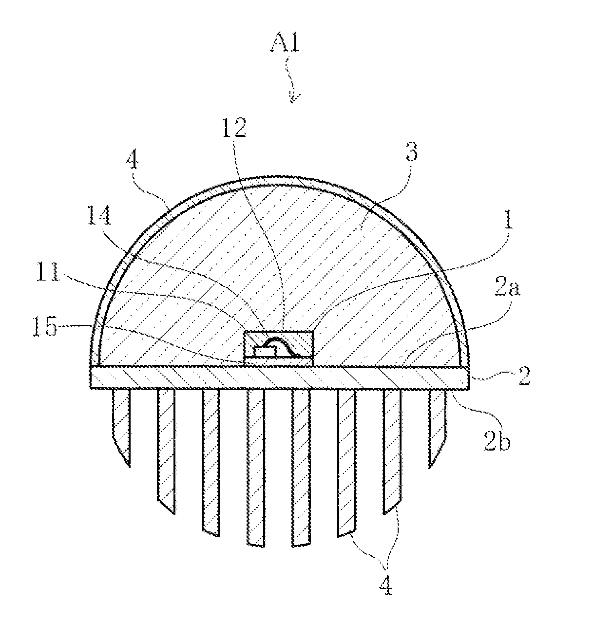
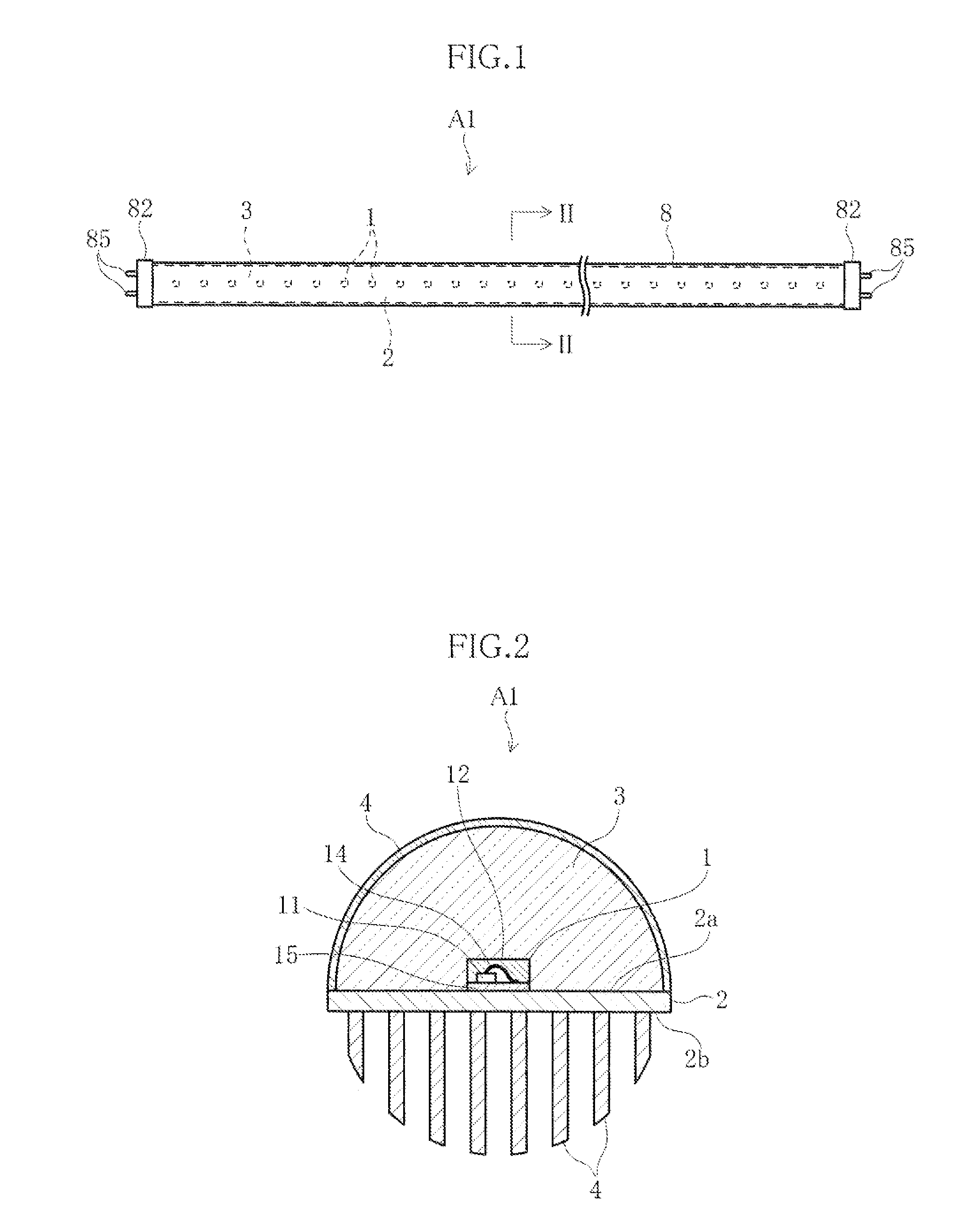
[0104]FIGS. 1 and 2 show an LED lamp according to the present invention. The LED lamp A1 of this embodiment includes a plurality of LED modules 1 serving as a light source, a substrate 2, a light guide 3, a light-transmitting cover 8, heat dissipation members 4 and bases 82, and has an elongated cylindrical shape as a whole. For instance, the LED lamp A1 is used as attached to a general-use fluorescent lighting fixture, as a substitute for e.g. a straight-tube fluorescent lamp.

[0105]The LED modules 1 are mounted on the substrate 2 at predetermined intervals in a row. As shown in FIG. 2, each of the LED modules 1 is made up of an LED bare chip 11, a resin package 12, a bonding wire 14 and a base member 15. For instance, the LED bare chip 11 is made of a GaN-based semiconductor and emits blue light. The resin package 12 is made of e.g. silicone resin that transmits light, and covers the LED bare chip 11. The resin package 12 contains a fluorescent material that emits yellow light when...

second embodiment

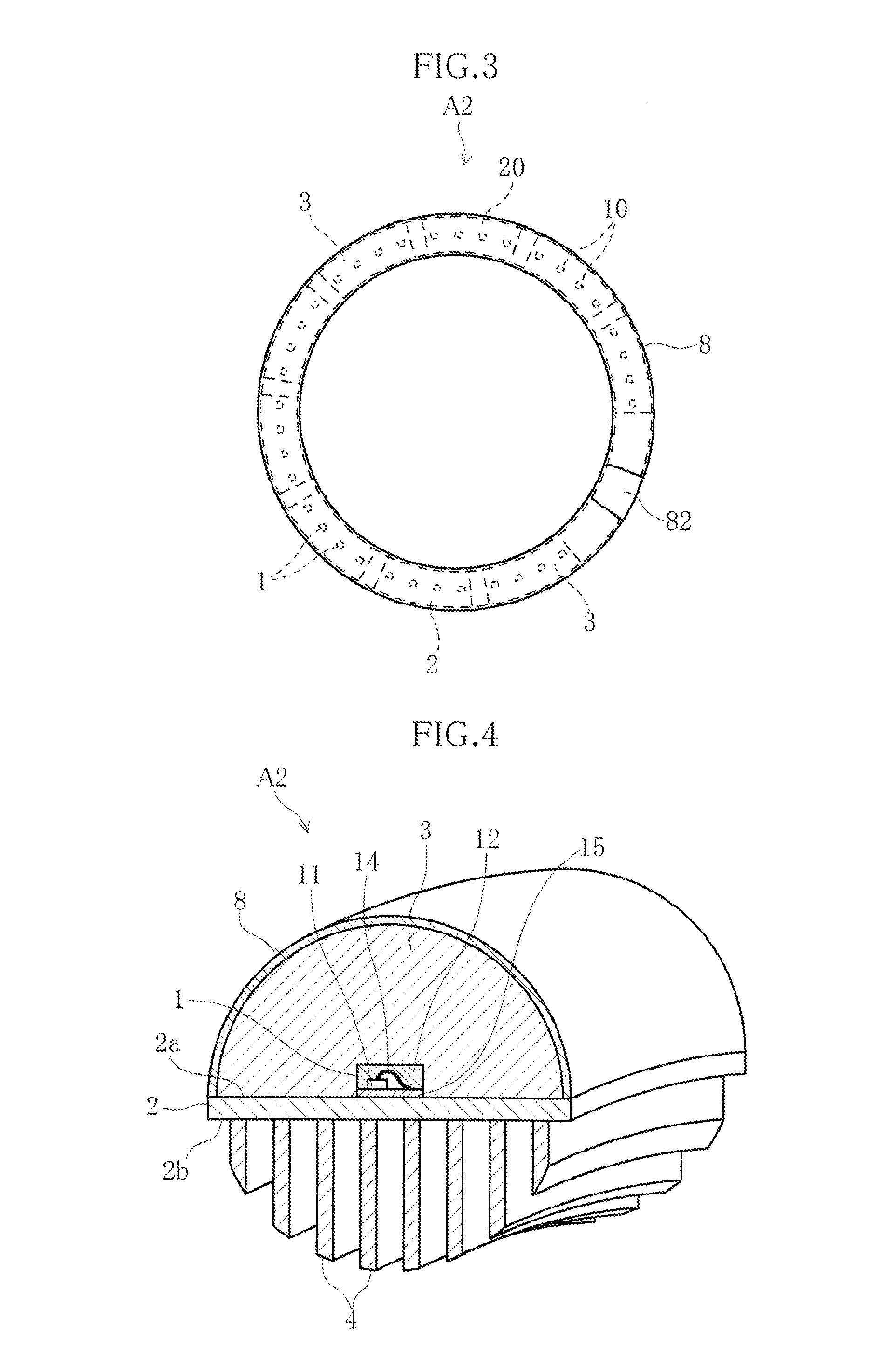
[0116]FIGS. 3 and 4 illustrate an LED lamp according to the present invention. The LED lamp A2 of this embodiment has an annular shape as a whole and is attached to a general-use fluorescent lighting fixture as a substitute for e.g. a circular fluorescent lamp. The light-transmitting cover 8 is annular as a whole and in the form of an arc of a semicircle in cross section. A plurality of substrates 2 are curved to conform to the shape of the light-transmitting cover 8. The substrates 2 are arranged along the light-transmitting cover 8. The gap between adjacent substrates 2 or between the substrate 2 and the base 82 may be filled by a plate-like spacer. The heat dissipation members 4 are curved to conform to the shape of the light-transmitting cover 8. Similarly to the foregoing embodiment, the light guide 3 is provided between the mount surfaces 2a of the substrates 2 and the light-transmitting cover 8 in close contact with these and the LED modules 1.

[0117]In the LED lamp A2 again, ...

third embodiment

[0118]FIG. 5 illustrates an LED lamp according to the present invention. The LED lamp A3 of this embodiment is different from the foregoing embodiments in that a light-transmitting cover is not provided and the LED modules 1 are covered only by the light guide 3. This LED lamp A3 allows further reduction of the number of the parts, which leads to further reduction of the cost.


PUM


Abstract

An LED lamp A1 includes a plurality of LED modules 1 and a substrate 2 on which the LED modules 1 are mounted in a row. A light guide 3 covering the LED modules 1 is provided on the substrate 2. The light guide 3 is held in close contact with each of the LED modules. With this arrangement, a proper amount of light is obtained with the use of a smaller number of LED modules 1 or with less power consumption.

Description

TECHNICAL FIELD[0001]The present invention relates to an LED lamp that uses a light emitting diode (hereinafter referred to as “LED”) as the light source and is attachable to a general-use fluorescent lighting fixture as a substitute for a fluorescent lamp.BACKGROUND ART[0002]FIG. 35 shows a conventional LED lamp (see Patent Document 1, for example). The LED lamp X illustrated in the figure includes a substrate 91 in the form of an elongated rectangle, a plurality of LEDs 92 mounted on the substrate 91, a tube 93 accommodating the substrate 91, and terminals 94. The substrate 91 is formed with a wiring pattern (not shown) connected to the LEDs 92 and the terminals 94. The LED lamp X is structured such that the LEDs 92 can be turned on when the terminals 94 are fitted into inlet ports of sockets of a general-use fluorescent lighting fixture.[0003]The general-use fluorescent lighting fixture herein refers to lighting fixtures widely used for interior lighting as the main application, ...

Claims


Application Information

Patent Timeline
Patent Type & Authority Applications(United States)
IPC IPC(8): F21V29/00F21V8/00F21V9/16H05B44/00
CPCF21K9/00F21K9/17F21K9/52F21Y2101/02F21Y2103/003F21V21/005G02B6/0003F21V23/026F21V29/70F21V29/75F21V29/763F21V29/767F21V29/83F21V29/004F21V19/002H05B45/50H01L2924/181H01L2224/48091F21K9/27F21K9/61F21Y2103/10F21Y2115/10F21K9/278H05B45/56H01L2924/00014H01L2924/00012F21V3/02F21V19/003F21V23/02
Inventor KAWABAT, YUSAKUFUKUMOTO, HIROSHIIEMOTO, TAKAOWATANABE, TOSHIOOSAWA, HIDEHARUFUKUI, HIROYUKISHIMIZU, HIROTAKA
Owner ROHM CO LTD
Why Eureka
Try Eureka