Lighting device

a technology light bulbs, which is applied in the direction of lighting and heating apparatus, instruments, optical elements, etc., can solve the problems of discoloration of light emitting devices, and achieve the effect of reducing discoloration

Inactive Publication Date: 2011-09-22
SIGNIFY HLDG BV
View PDF10 Cites 36 Cited by
  • Summary
  • Abstract
  • Description
  • Claims
  • Application Information

AI Technical Summary

Benefits of technology

[0003]In view of the above, an objective of the invention is to solve or at least reduce the problems discussed above. In particular, an objective is to reduce discoloration, especially for colors in a mid-wavelength range of the lighting device. Here, a mid-wavelength range should be construed as a wavelength range within a total wavelength range of light emitted by the lighting device, wherein the mid-wavelength has neighboring wavelength ranges having shorter and longer wavelengths, respectively, than the wavelengths in the mid-range wavelength range.

Problems solved by technology

There may be effects of discoloration with light emitting devices as the one disclosed in WO 2006 / 129220 A1, especially at large angles of light spread.

Method used


Image

  • Lighting device
  • Lighting device
  • Lighting device

Examples


Embodiment Construction

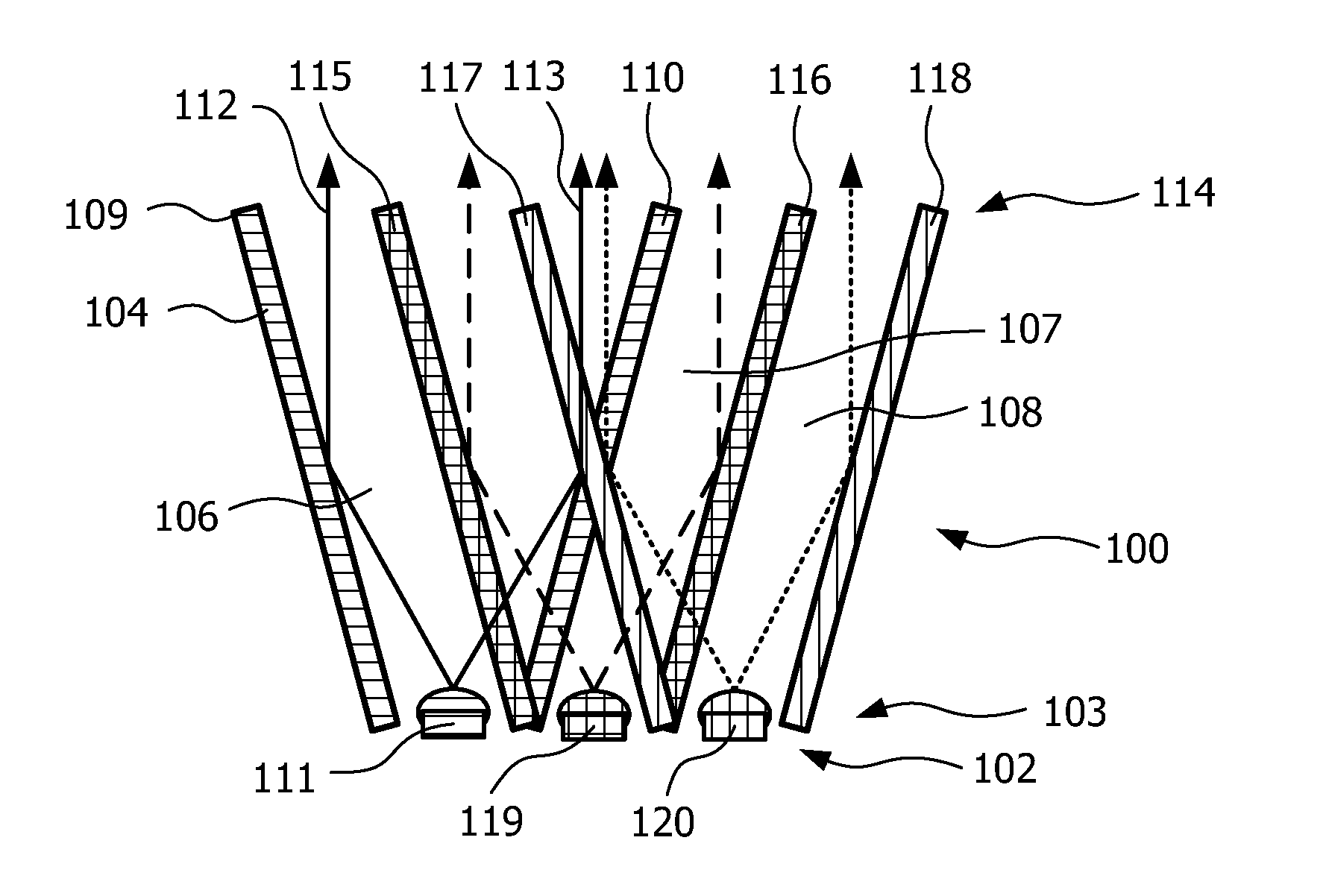
[0028]FIG. 1 schematically illustrates a lighting device 100 comprising a plurality of light sources 102 each having different wavelength ranges such that the lighting device 100 is able to provide light with desired color properties, e.g. white light with a preferred color temperature or colored light. Choice and control of the light sources 102 to achieve the preferred color temperature or color of light are known within the art, and is not a part of the present invention. However, for the purpose of better understanding, it should be noted that the light sources 102 can advantageously comprise light emitting diodes (LEDs), for example providing red, green and blue light, respectively. The light sources 102 are arranged at a receiving end 103 of a collimating means 104 of the lighting device 100.

[0029]Thus, the lighting device 100 comprises the collimating means 104 comprising a sub-collimator 106, 107, 108 for each of the light sources 102. For the understanding of the invention,...


PUM


Abstract

A lighting device (100, 200, 300, 400) is disclosed. The device comprises a plurality of light sources (111, 119, 120, 211, 219, 220) providing light in different wavelengths, a collimating means (104, 204) having a receiving end (103, 203, 407) and an output end (114, 214, 409), wherein said light sources are arranged at said receiving end. The collimating means comprises a set of wavelength selective filters (109, 110, 115, 116, 117, 118, 215, 217) arranged as sub-collimators (106, 107, 108, 206, 207, 208) to each of said plurality of light sources such that, for each light source, said sub-collimator collimates the light from its light source, and said wavelength selective filter of said each light source is translucent for light from adjacent light sources of different wavelength, wherein said wavelength selective filters are high pass or low pass filters.

Description

TECHNICAL FIELD[0001]The present invention relates to a lighting device. In particular, the present invention relates to a lighting device having a set of wavelength selective filters arranged as sub-collimators to collimate light from a plurality of light sources.BACKGROUND OF THE INVENTION[0002]WO 2006 / 129220 A1 discloses a light emitting device comprising collimating means comprising filters reflecting light of certain properties towards an output area of the collimating means. There may be effects of discoloration with light emitting devices as the one disclosed in WO 2006 / 129220 A1, especially at large angles of light spread. It is therefore a desire to provide an improved lighting device.SUMMARY OF THE INVENTION[0003]In view of the above, an objective of the invention is to solve or at least reduce the problems discussed above. In particular, an objective is to reduce discoloration, especially for colors in a mid-wavelength range of the lighting device. Here, a mid-wavelength ...

Claims


Application Information

Patent Timeline
Patent Type & Authority Applications(United States)
IPC IPC(8): F21V9/00
CPCG02B27/1006G02B27/145G02B19/0019G02B19/0066G02B27/149
Inventor VAN GORKOM, RAMON PASCALHOELEN, CHRISTOPH GERARD AUGUSTVAN AS, MARCOMUTSAERS, CORNELIS ADRIANUS HENRICUS ANTONIUSCOOIJMANS, HUIB
Owner SIGNIFY HLDG BV
Why Eureka
Try Eureka