Blur function modeling for depth of field rendering

a function modeling and depth of field technology, applied in the field of image capture devices, can solve the problems of having severely limited aperture sizes, obtaining sufficient lighting to capture images, and not making a small aperture lens equal to a conventional large aperture lens

Active Publication Date: 2011-09-22
SONY CORP
View PDF13 Cites 40 Cited by
  • Summary
  • Abstract
  • Description
  • Claims
  • Application Information

AI Technical Summary

Benefits of technology

[0039]FIG. 4 is a 3D graph of a Gaussian filter for applying a selec

Problems solved by technology

Although small to medium sized cameras have become extremely popular with regard to their light weight, portability and low cost, they typically suffer from having severe

Method used


Image

  • Blur function modeling for depth of field rendering
  • Blur function modeling for depth of field rendering
  • Blur function modeling for depth of field rendering

Examples


embodiment 1

[0107]2. An apparatus , wherein said apparatus generates a digital image captured with said imaging element at a first aperture setting which appears as if it has been captured at a second aperture setting which is larger than said first aperture setting.

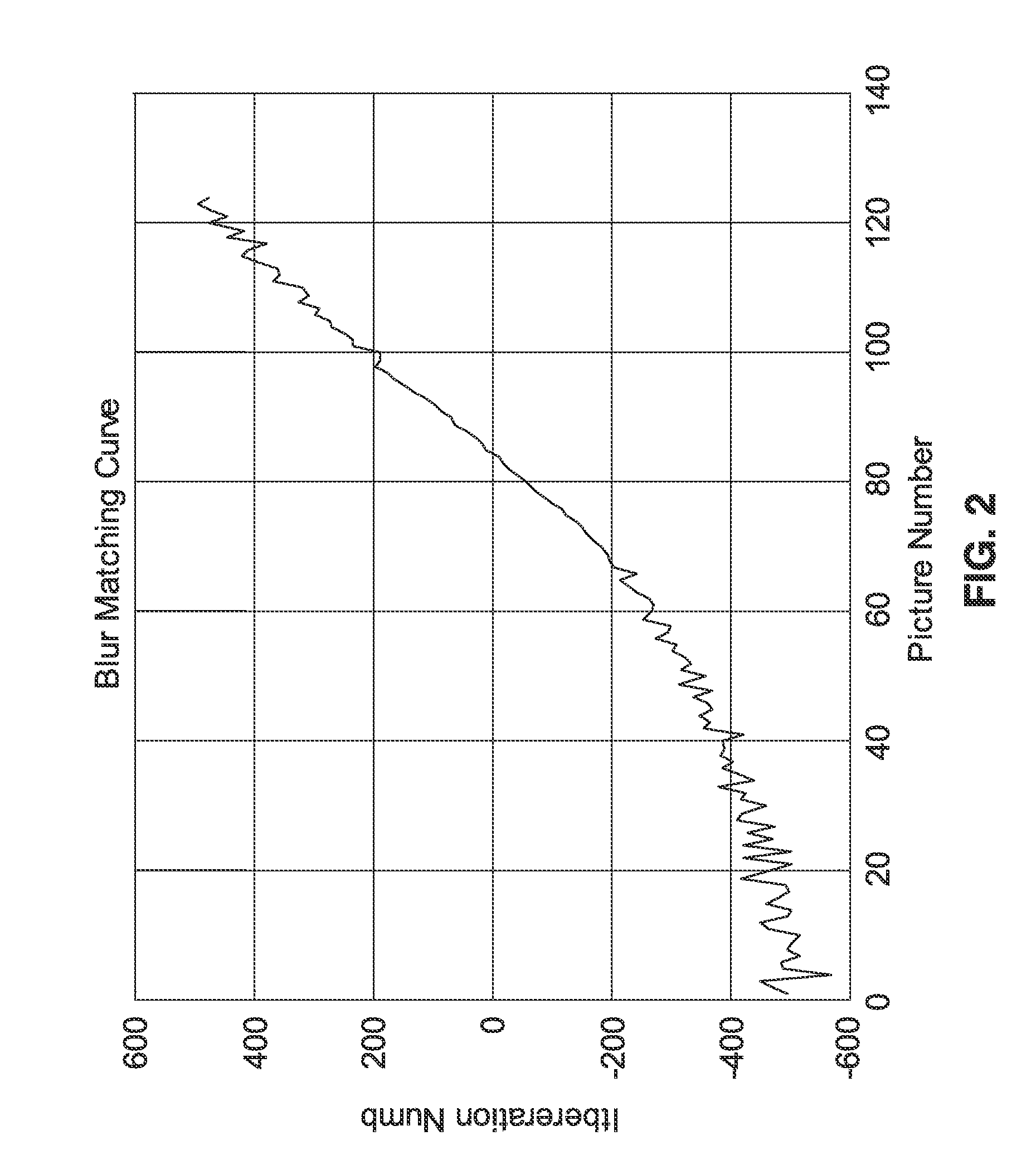
[0108]3. An apparatus according to embodiment 1, wherein said matching curve is retained in the memory of said apparatus in response to capturing a sequence of images across a focal range of the apparatus to establish a relationship between iteration number and lens focus position.

[0109]4. An apparatus according to embodiment 1, wherein an amount of said defocus blur for an image can be determined in response to said matching curve by summing iteration numbers in an interval between an in-focus, first position, and a second position.

[0110]5. An apparatus according to embodiment 1, wherein slope of said matching curve is inversely proportional to f-number squaring.

[0111]6. An apparatus according to embodiment 1, wherein said defocus ...

embodiment 13

[0119]14. An apparatus , wherein said apparatus generates a digital image output captured with said imaging element at a first aperture setting which appears as if captured at a second aperture setting which is larger than said first aperture setting.

[0120]15. An apparatus according to embodiment 13, wherein said matching curve is retained in the memory of said apparatus in response to capturing a sequence of images across a focal range of the apparatus to establish a relationship between iteration number and lens focus position.

[0121]16. An apparatus according to embodiment 13, wherein in response to said matching curve, an amount of defocus blur of an image can be computed as a sum of iteration numbers in an interval between an in-focus position, first position, and a second position.

[0122]17. An apparatus according to embodiment 13, wherein slope of said matching curve is inversely proportional to f-number squaring.

[0123]18. An apparatus according to embodiment 13, wherein said d...

embodiment 23

[0129]24. A method , further comprising detecting user input for selecting a digital aperture size, or a mode associated with use of said digital aperture size, which exceeds the physical aperture sizing which is attainable.


PUM


Abstract

A method and apparatus of depth of field rendering which simulates larger apertures for images captured at a smaller aperture. The depth of field rendering provides selective simulation of out-of-focus effects which are attainable with cameras having a larger aperture when capturing images at a smaller aperture. A blur function model is created based on the relationship between the blur change and the aperture change. This model is used to determine the blur difference which would arise between two images taken at two different apertures. Then the out-of-focus effect is generated by blurring the image in a rendering process based on the blur difference.

Description

CROSS-REFERENCE TO RELATED APPLICATIONS[0001]Not ApplicableSTATEMENT REGARDING FEDERALLY SPONSORED RESEARCH OR DEVELOPMENT[0002]Not ApplicableINCORPORATION-BY-REFERENCE OF MATERIAL SUBMITTED ON A COMPACT DISC[0003]Not ApplicableNOTICE OF MATERIAL SUBJECT TO COPYRIGHT PROTECTION[0004]A portion of the material in this patent document is subject to copyright protection under the copyright laws of the United States and of other countries. The owner of the copyright rights has no objection to the facsimile reproduction by anyone of the patent document or the patent disclosure, as it appears in the United States Patent and Trademark Office publicly available file or records, but otherwise reserves all copyright rights whatsoever. The copyright owner does not hereby waive any of its rights to have this patent document maintained in secrecy, including without limitation its rights pursuant to 37 C.F.R. §1.14.BACKGROUND OF THE INVENTION[0005]1. Field of the Invention[0006]This invention pert...

Claims


Application Information

Patent Timeline
IPC IPC(8): G06K9/40
CPCG06T5/002G06T2207/20021G06T2207/20012G06T5/20H04N5/2621H04N23/80H04N23/743
Inventor LI, PINGSHANALI, GAZI
Owner SONY CORP
Why Eureka
Try Eureka