
Blank with coding for the production of tooth-technical shaped parts and procedures for the identification of a blank

a technology of coding and coding means, applied in the field of coding for the production of tooth-technical shaped parts and procedures for the identification of blanks, can solve the problems of unguaranteed reliability, redundancy of recognition units, dirty environment, etc., and achieve the effects of improving enhancing the accuracy of identification, and ensuring the reliability of methods

Active Publication Date: 2011-09-22
SIRONA DENTAL SYSTEMS
View PDF7 Cites 9 Cited by
  • Summary
  • Abstract
  • Description
  • Claims
  • Application Information

AI Technical Summary

Benefits of technology

[0020]The provision of structures showing various differences in level relative to the surface makes it possible to generate more complex coding. In this way, the coding means shows different differences in level between different panels.
[0054]Advantageously, to each panel incorporating a structure there can be assigned exactly one panel at surface level, the two panels forming a pair. This ensures that each panel incorporating a structure can be queried by the present method, which enhances the precision of identification.

Problems solved by technology

The drawbacks of such identification means are that the recognition unit is a redundant component, since it is not required for processing the workpiece.
Furthermore, the identification of a blank is easy to by-pass by using a sticker made by a photocopying process and placed on the blank and does not guarantee reliable results in a dirty environment without previous cleaning.
Furthermore, the restriction of recognition to the machining chamber of the machine tool requires additional effort.
Furthermore, there is no guarantee that recognition will succeed in a dirty environment without prior cleaning.
The sensors or analyzing processes necessary for such methods are not required for machining the workpiece and thus represent a high cost factor for the machine tool.
Furthermore, recognition in a dirty environment without previous cleaning is not guaranteed.

Method used


Image

  • Blank with coding for the production of tooth-technical shaped parts and procedures for the identification of a blank
  • Blank with coding for the production of tooth-technical shaped parts and procedures for the identification of a blank

Examples


Embodiment Construction

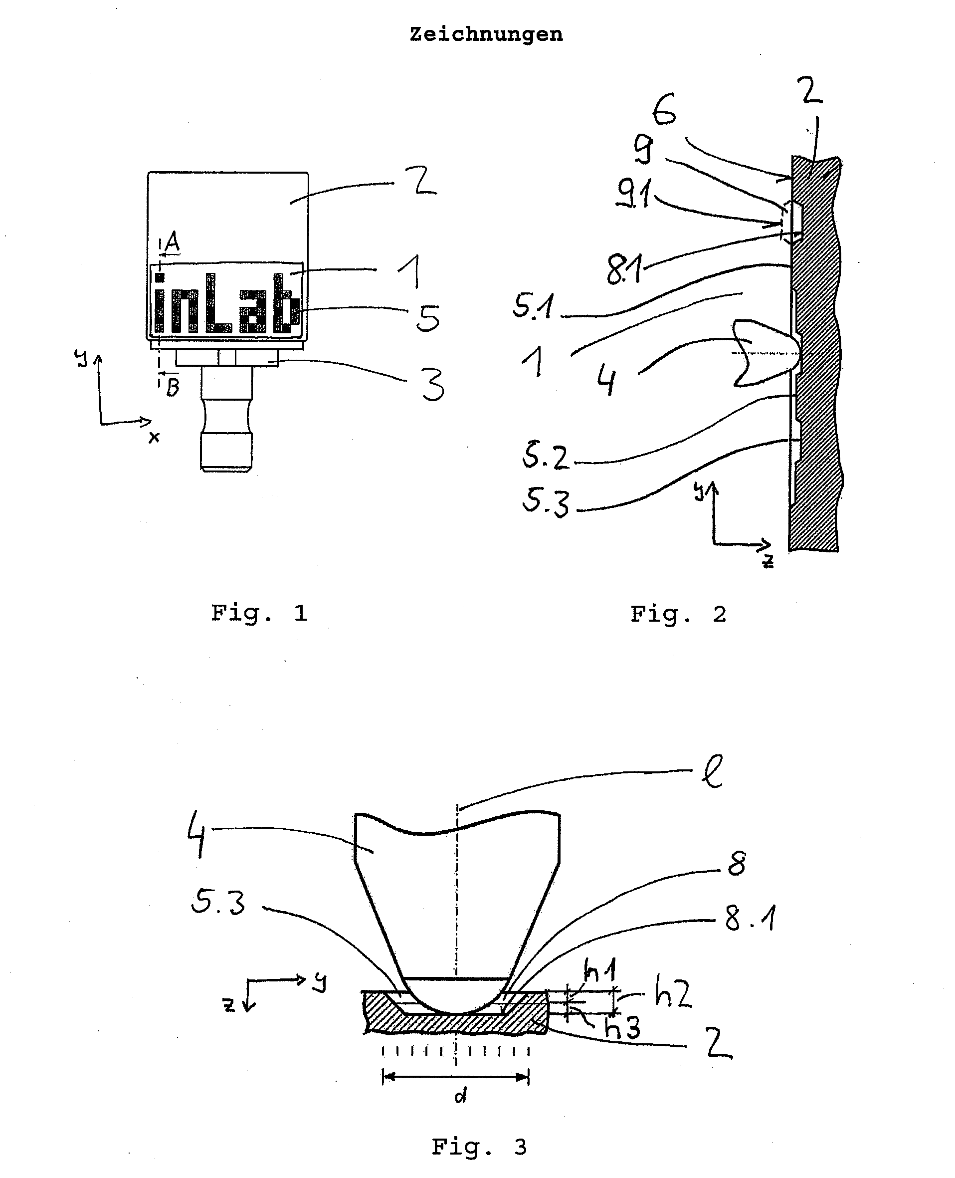
[0061]FIG. 1 illustrates a blank consisting of a corpus 2 disposed in a holder 3. The corpus 2 has coding means 1, which are three-dimensionally designed and disposed at that end of the blank corpus 2 that is near to the holder such that it can be scanned and uniquely identified with the aid of the existing machining tools 4 or by means of calibrating or positioning aids, such as is illustrated in FIGS. 2 and 3.

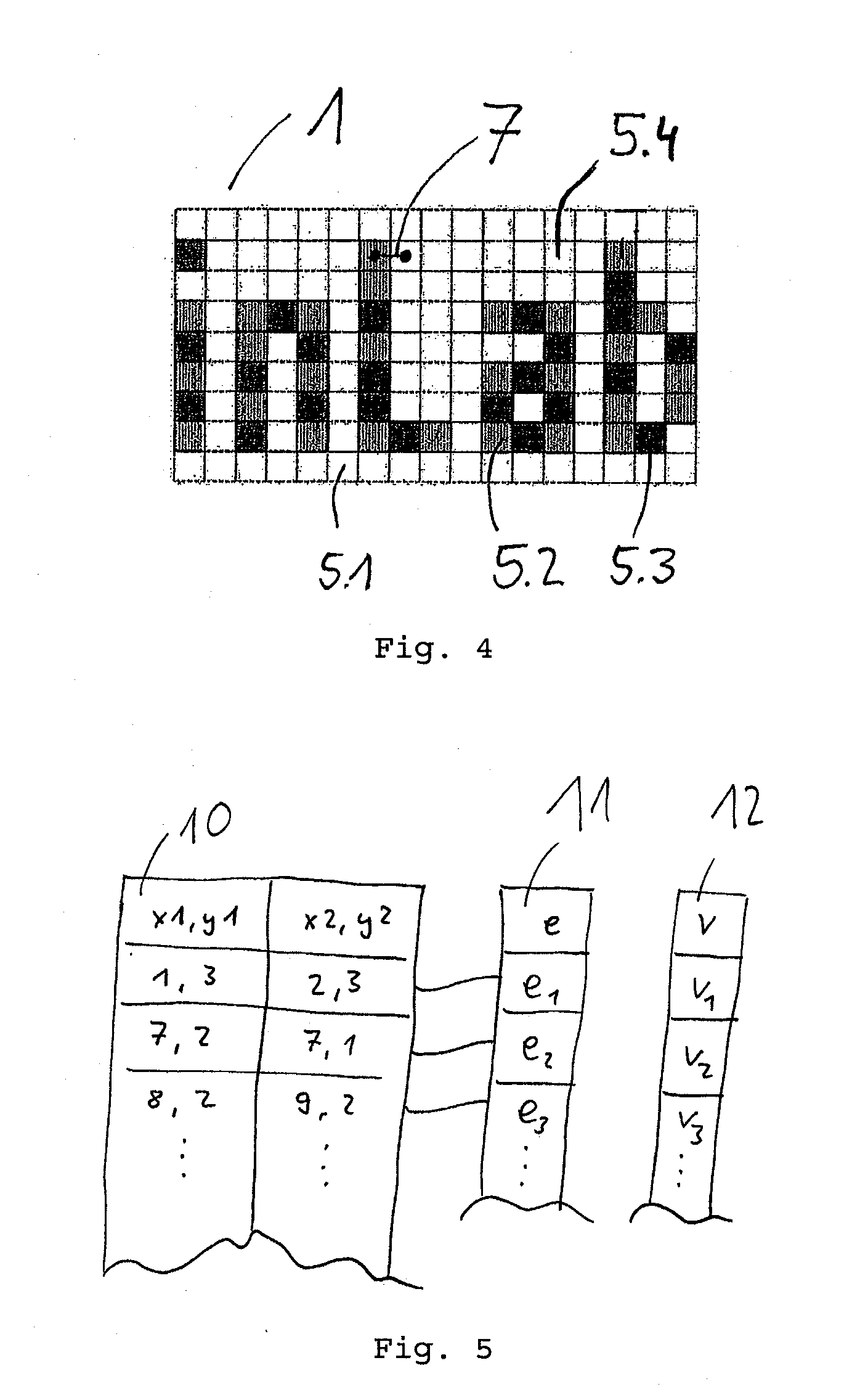
[0062]The coding means 1 is for this purpose formed according to the invention as a flat area extending in an x,y plane on the corpus 2, which coding means is divided, for example, into uniform panels 5, as outlined in FIG. 4.

[0063]FIG. 2 is a cross-section of a blank corpus 2 as shown in FIG. 1 and taken along the line AB. It can be seen that some of the panels 5.2, 5.3 are formed as structures 8, 9, for example, taking the form of depressions 8 relative to the surface 6 and having a base 8.1 below the level of the surface as regarded in the direction of the z axis. The stru...


PUM


Abstract

The invention relates to a blank for the production of a dental shaped body, wherein the blank has a corpus (2) of tooth restoration material, from which the shaped part to be fabricated is carved by means of a tool (4) by removal of material. The blank has coding means (1) formed on part of the surface (6) of the blank corpus (2), which coding means (1) has at least one structure (8, 9) for identification of the blank. The coding means (1) consists of a plurality of panels (5.1) at the level of the surface (6) of the corpus (2) and a plurality of panels (5.2, 5.3) incorporating a flat structure (8, 9) at a level (h1, h2) which is distinguishable from at least the level of the surface (6) of the corpus (2).The invention further relates to a method for identifying a blank with the aid of coding means (1).

Description

BACKGROUND OF THE INVENTION[0001]The invention relates to a blank comprising coding means for the production of dental shaped bodies and a method for recognizing a blank by coding means.PRIOR ART[0002]A recognition unit is used for the identification of objects, which unit is not required for processing said objects.[0003]Identification means involving relatively low technical elaboration is described in DE 10 2007 018 594 A1. In this case recognition of a sequence of alphanumeric characters disposed on a workpiece is carried out by means of an optical recognition unit followed by image recognition involving character recognition.[0004]The drawbacks of such identification means are that the recognition unit is a redundant component, since it is not required for processing the workpiece. Furthermore, the identification of a blank is easy to by-pass by using a sticker made by a photocopying process and placed on the blank and does not guarantee reliable results in a dirty environment ...

Claims


Application Information

Patent Timeline
IPC IPC(8): A61C13/00A61C13/20
CPCA61C13/0022A61C13/0009A61C2201/002G06K19/06121
Inventor NIEWIADOMSKI, KLAUS
Owner SIRONA DENTAL SYSTEMS
Learn More