

Control Apparatus for and Control Method of Controlling Variable Valve Mechanism in Hybrid Vehicle
- Summary
- Abstract
- Description
- Claims
- Application Information
AI Technical Summary
Benefits of technology
Problems solved by technology
Method used
Image

Examples
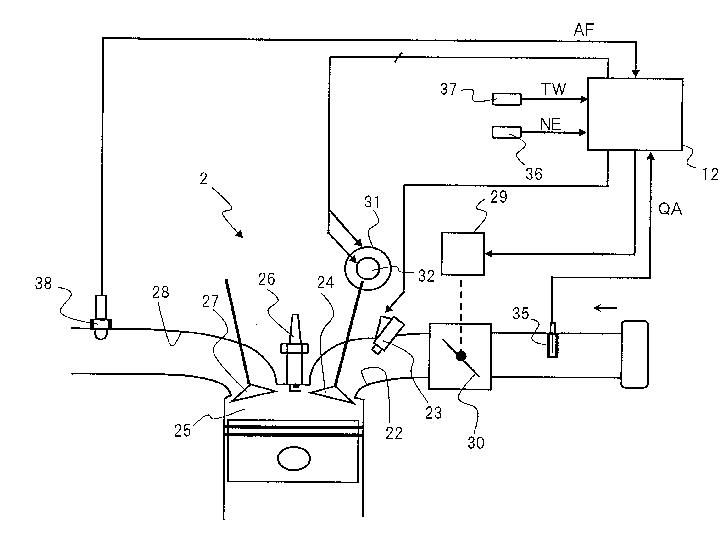
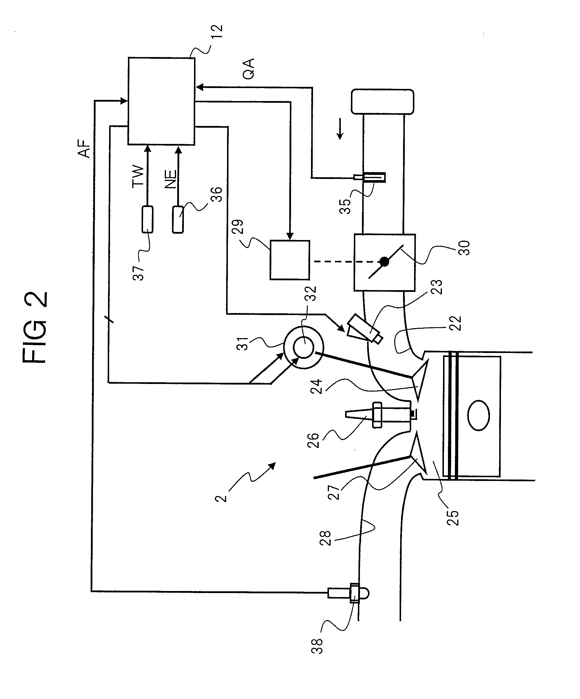
Embodiment Construction
lass="d_n">[0018]FIG. 4 is a flowchart illustrating control of an intake valve closing timing according to an embodiment of the invention;
[0019]FIG. 5 is a time chart illustrating change of a closing timing during a period from engine stop to engine start; and
[0020]FIG. 6 is a time chart illustrating a closing timing at engine start and change of engine rotating speed according to an embodiment of the invention.
DESCRIPTION OF THE PREFERRED EMBODIMENTS
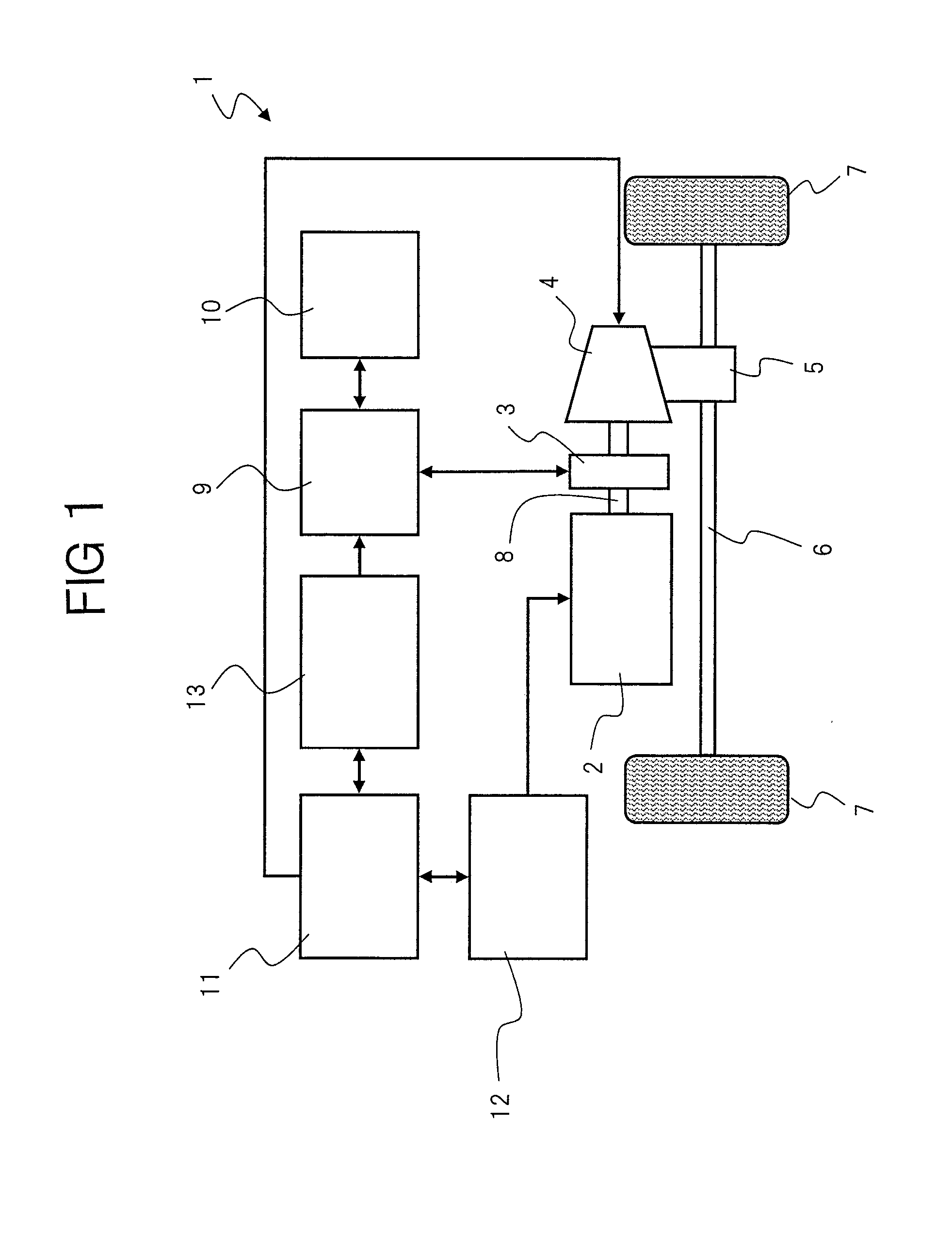
[0021]FIG. 1 illustrates a general configuration of a drive of a hybrid vehicle according to an embodiment of the invention.
[0022]A hybrid vehicle 1 illustrated in FIG. 1 has both an engine 2 and an electric motor 3 as drive sources for running a vehicle.
[0023]The driving force exerted by the engine 2 is transferred to driving wheels 7 and 7 via a transmission 4, a differential gear 5, and an axle 6.
[0024]A rotor of electric motor 3 is directly connected to an output shaft 8 between engine 2 and transmission 4.
[0025]Output shaft 8 and t...
PUM
 Abstract
Description
Claims
Application Information