Power management method and related power management system

a power management system and power management technology, applied in the direction of power supply for data processing, instruments, measurement devices, etc., can solve the problems of prohibitive cost and more complexity

Active Publication Date: 2011-09-22
I O INTERCONNECT LTD
View PDF11 Cites 112 Cited by
  • Summary
  • Abstract
  • Description
  • Claims
  • Application Information

AI Technical Summary

Benefits of technology

[0013]It is thereof an objective of the present invention to provide a power management method for switching the computer system between system modes associated with power utilization.

Problems solved by technology

Consequently, this may lead to more complexities and prohibitive cost.

Method used


Image

  • Power management method and related power management system
  • Power management method and related power management system
  • Power management method and related power management system

Examples


Embodiment Construction

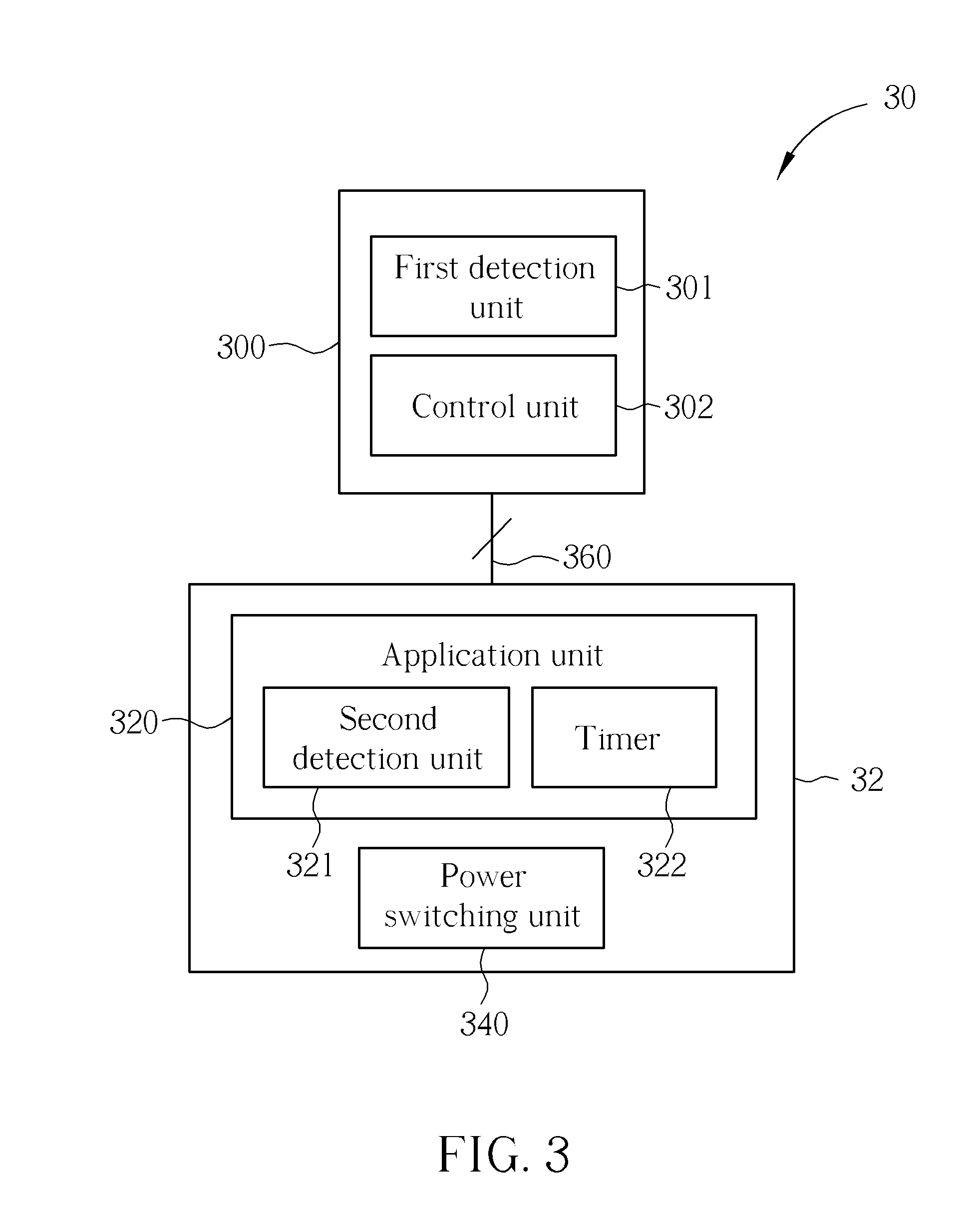
[0024]Please refer to FIG. 3, which illustrates a power management system 30 according to an example. The power management system 30 may be applied to a computer system 32. The computer system can be operated in a mode M1 and a mode M2. The power management system 30 is used for switching the computer system 32 between the modes M1 and M2 for power-saving purpose. The modes M1-M2 can control the computer system 32 to operate in different power degrees and may be a standby mode, full-power mode, low power mode, sleep mode, etc. The computer system 32 may be, but is not limited to, a digital camera, a personal assistant (PDA), a smart phone, a personal computer (PC), a laptop / desktop, a digital video device, and a portable audio device. The power management 30 includes a human interface device (HID) 300, an application unit 320, a power switching unit 340, and a data bus 360. The data bus 360 is used for communicating the HID 300 with the computer system 32. The data bus 360 may be re...


PUM


Abstract

A power management method is disclosed. The power management method comprises the step of a computer system checking existence of a manufacturing identifier (ID) of a human interface device (HID) when the computer system is operated in a first mode; the computer system continuously detecting whether the HID exist when the manufacturing ID exists; the computer system starting a timer when the computer system detects that the HID does not exist; the computer system entering a second mode when the timer expires; the HID determining whether the computer system is operated in the second mode, when plugged into the computer system; the HID performing state transition on the computer system when determining that the computer system is in the second mode; and the computer system entering the first mode when detecting the state transition.

Description

BACKGROUND OF THE INVENTION[0001]1. Field of the Invention[0002]The present invention relates to a power management method and related power management system, and more particularly, to a power management method for switching a power mode of a computer system and related power management system.[0003]2. Description of the Prior Art[0004]Universal serial bus (USB) was developed to define an external expansion bus which facilitates the connection of additional peripherals to a computer system. The USB technique is implemented by personal computer (PC) host controller hardware and software and by peripheral friendly master-slave protocols and achieves robust connections and cable assemblies, which USB systems are extendable through multi-port USB dock station.[0005]In USB systems, the role of the system software is to provide a uniformed view of the input / output architecture for all applications software by hiding hardware implementation details. In particular, it manages the dynamic a...

Claims


Application Information

Patent Timeline
Patent Type & Authority Applications(United States)
IPC IPC(8): G06F1/32G06F1/26G06F13/38
CPCG06F1/1632G06F1/3215G06F1/3203
Inventor KAKISH, MUSA IBRAHIMZEUNG, PING-SHUNCHEN, JOHNNY HSIANG-YU
Owner I O INTERCONNECT LTD
Why Eureka
Try Eureka