
Nebulizing assembly

a technology of nebulizing assembly and nozzle, which is applied in the direction of moving spraying apparatus, spraying apparatus, spray nozzle, etc., can solve the problems of not considering the manufacturing cost and the working performance at the same time, and achieves the effects of minimizing resistance, high bonding force and good operation

Inactive Publication Date: 2011-09-29
MICRO BASE TECH CORP
View PDF2 Cites 38 Cited by
  • Summary
  • Abstract
  • Description
  • Claims
  • Application Information

AI Technical Summary

Benefits of technology

[0004]A primary object of the present invention is to provide a nebulizing assembly to eliminate the drawbacks in the currently available nebulizing assemblies.
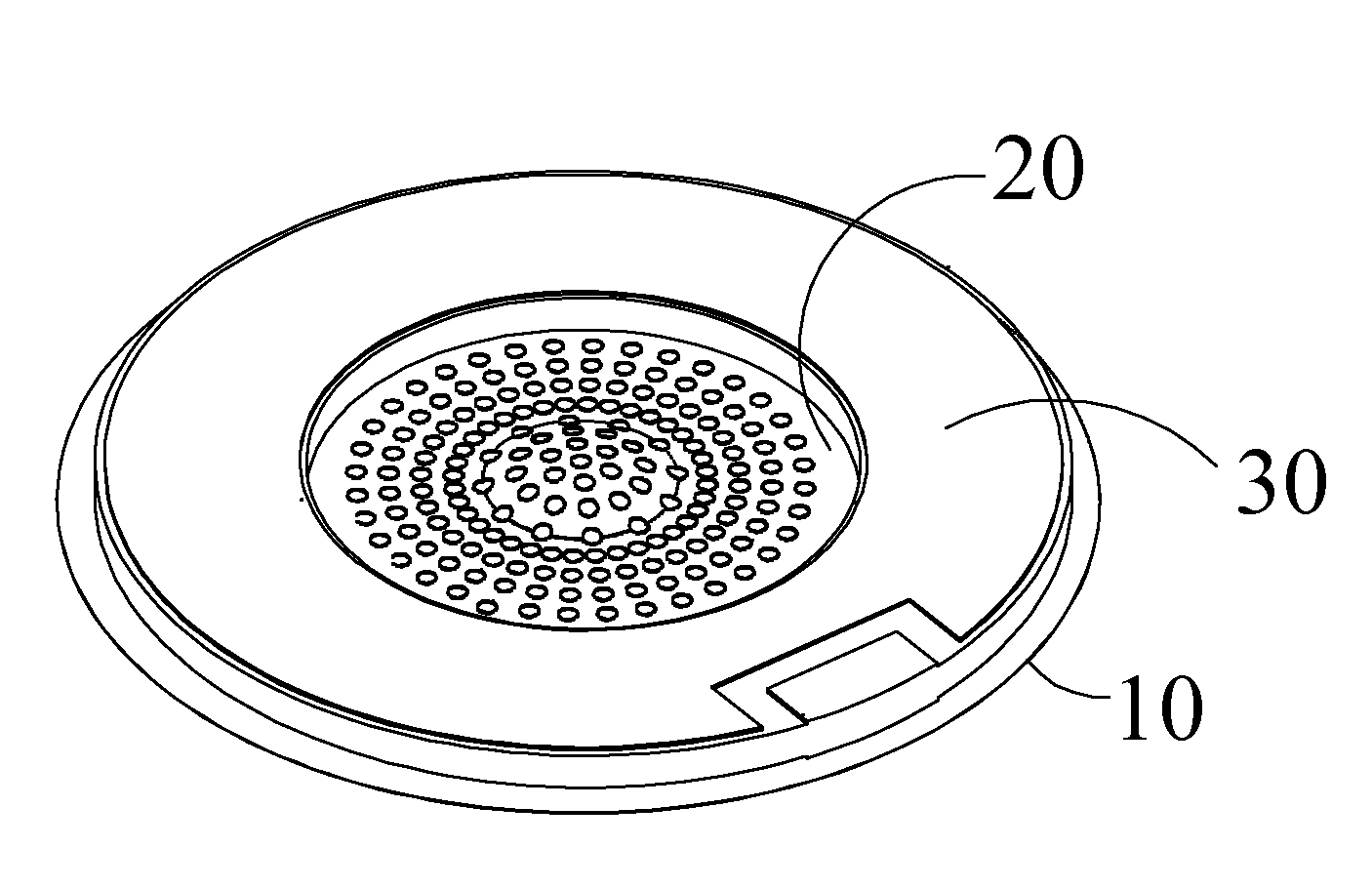
[0006]In gluing the nebulizing plate between the base and the piezoelectric driving element, the adhesive medium applied over the gluing section will flow into and fill up all the glue holes in the gluing section to form a glue layer. When the glue layer becomes dried, an extremely high bonding force can be provided between the dried glue layer and the nebulizing plate, preventing the glue layer from being structurally damaged when the whole nebulizing assembly vibrates to spray mist at high speed. In addition, since the mist outlet on the piezoelectric driving unit and the through hole on the base have the same diameter, it is able to minimize the resistance resulted from the fully packaged structure of the nebulizing assembly supplied to the nebulizing plate and to ensure good operation of the present invention in its actual applications. Further, the nebulizing plate in the present invention can provide good vibrating performance because it is not excessively clamped in place by other fixtures.

Problems solved by technology

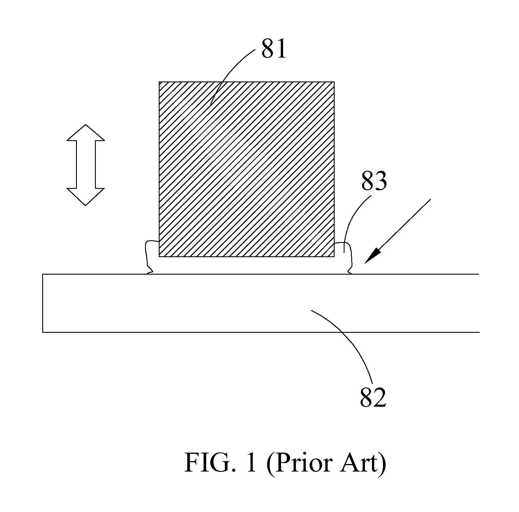
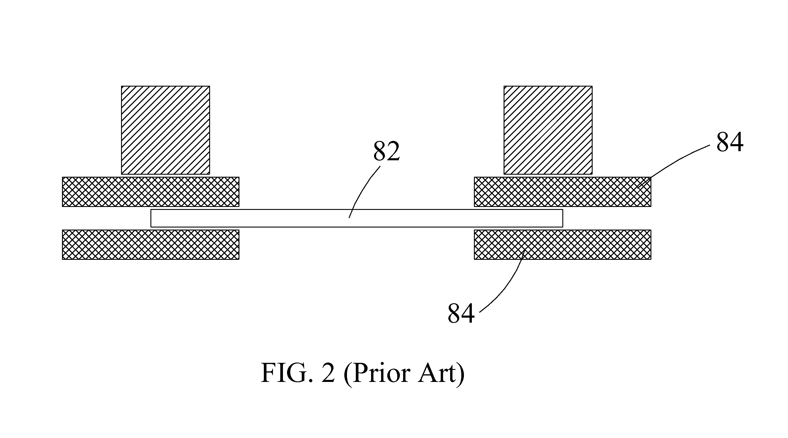
Therefore, the design of the nebulizing assembly of FIG. 2 fails to consider the manufacturing cost and the working performance at the same time.

Method used


Image

  • Nebulizing assembly
  • Nebulizing assembly
  • Nebulizing assembly

Examples


Embodiment Construction

[0012]The present invention will now be described with a preferred embodiment thereof. It is understood the accompanying drawings are illustrated only for assisting in describing the preferred embodiment of the present invention and is not necessarily in compliance with the exact or precise size proportion and part arrangement of a real product manufactured through implementing the present invention. Therefore, the size proportion and part arrangement shown in the accompanying drawings are not intended to limit the present invention, which is limited only by the appended claims.

[0013]Please refer to FIGS. 3 to 5. The present invention relates to a nebulizing assembly applicable to a nebulizer. Through piezoelectric conversion, the nebulizing assembly produces high-frequency vibration to oscillate a working liquid in the nebulizer, such that vapor mist is produced and forced out of the nebulizer. In a preferred embodiment of the present invention, the nebulizing assembly includes a b...


PUM


Abstract

A nebulizing assembly includes a base having a centered through hole; an nebulizing plate disposed on the base, the nebulizing plate having a radially outer area formed as a gluing section provided with a plurality of glue holes and a central area formed as a spraying section corresponding to the through hole on the base; and a piezoelectric driving element stacked on a top of the nebulizing plate and attached to the gluing section, and having a centered mist outlet. A glue layer is applied over the gluing section to fill up all the glue holes and can provide an extremely high bonding force when becoming dried to thereby firmly bond the nebulizing plate between the base and the piezoelectric driving element. The mist outlet and the through hole on the base have the same diameter to enable minimized resistance applied the whole structure to the nebulizing plate.

Description

FIELD OF THE INVENTION[0001]The present invention relates to a nebulizing assembly, and more particularly to a device that oscillates at high speed to convert a working liquid into mist for use.BACKGROUND OF THE INVENTION[0002]The conversion of a working liquid into mist by way of high-speed vibration has been widely applied in medicine or aromatizing agent dispersion. To do so, a nebulizing assembly is provided in a nebulizer at a working liquid pumping end thereof. Through piezoelectric conversion, the nebulizing assembly produces high-frequency micro-amplitude vibration waves to thereby cut the surface of the working liquid, so that fine mist with vectored impact is formed. And, as a result of Brownian motion effect, aromatizing agent can be mixed into air to change the property of air, or medication in the form of mist can be produced for inhalation therapy. In addition to the applications of forming aromatized air and producing medication in the form of mist, the nebulizing ass...

Claims


Application Information

Patent Timeline
IPC IPC(8): B05B1/08
CPCB05B17/0646
Inventor LIN, CHIEN-HUAHUANG, CHIA-CHENLIU, LIANG-WEILIN, TAI-SHUANHSU, YU-CHUNGHSIUNG, CHIEH-MINGHUANG, MEI-HUI
Owner MICRO BASE TECH CORP
Learn More