Illuminating apparatus

a technology of illumination apparatus and light source, which is applied in the direction of lighting and heating apparatus, point-like light source, semiconductor devices for light sources, etc., to achieve the effect of high heat dissipation characteristics and low cos

Active Publication Date: 2011-09-29
PANASONIC CORP
View PDF14 Cites 28 Cited by
  • Summary
  • Abstract
  • Description
  • Claims
  • Application Information

AI Technical Summary

Benefits of technology

[0016]According to the first aspect of the present invention, the light of the light-emitting device is emitted from the opening of the heat dissipator that is in one of a bottomed cylindrical shape and a bowl shape, and also leaked outside the heat dissipator through the one or more windows provided in the circumferential wall portion of the heat dissipator. Therefore, the lighting apparatus according to the first aspect of the present invention is suitable as a substitute for a conventional halogen lamp when positively utilizing leaked light.
[0017]Also, according to the second aspect of the present invention, the reflector is made of one of resin and glass. This makes it easy to form the facets on the base. Furthermore, since the heat dissipator 12 and the reflector 30 are separate members, a structure is possible where the heat dissipator 12 is commonly used while the reflector 30 is different depending on a light distribution pattern. This makes it possible to control light distribution at lower cost than a conventional structure, while maintaining high heat dissipation characteristics.

Problems solved by technology

Therefore, in the practical application of an LED lighting apparatus, it is an important issue to improve heat dissipation characteristics without violating the size limitation, which requires the LED lighting apparatus to have a size attachable to existing equipment.

Method used


Image

  • Illuminating apparatus
  • Illuminating apparatus
  • Illuminating apparatus

Examples


embodiment 1

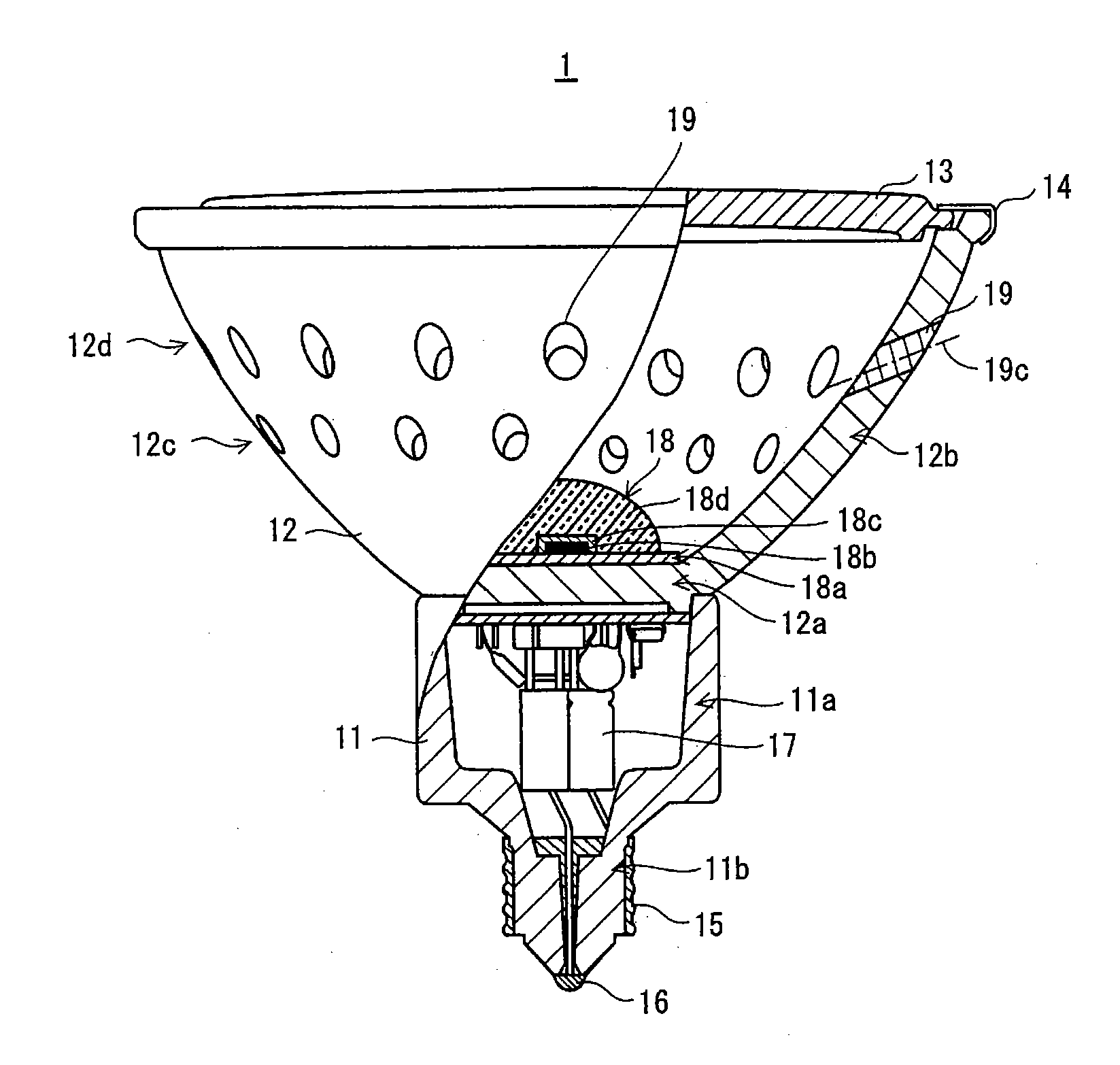
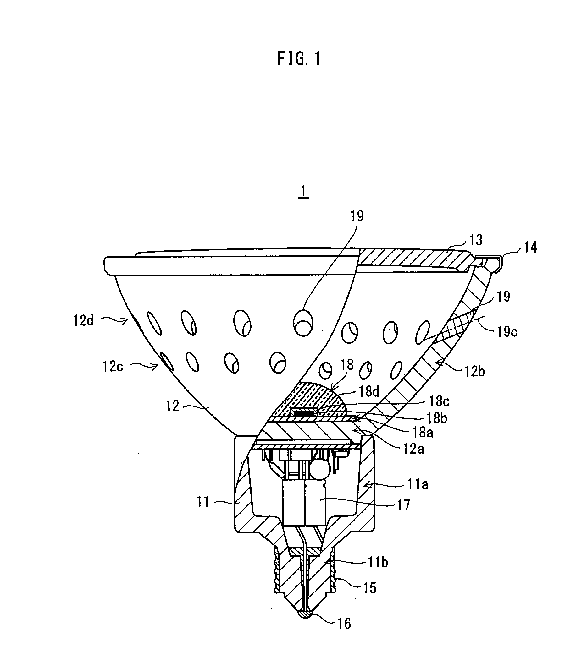
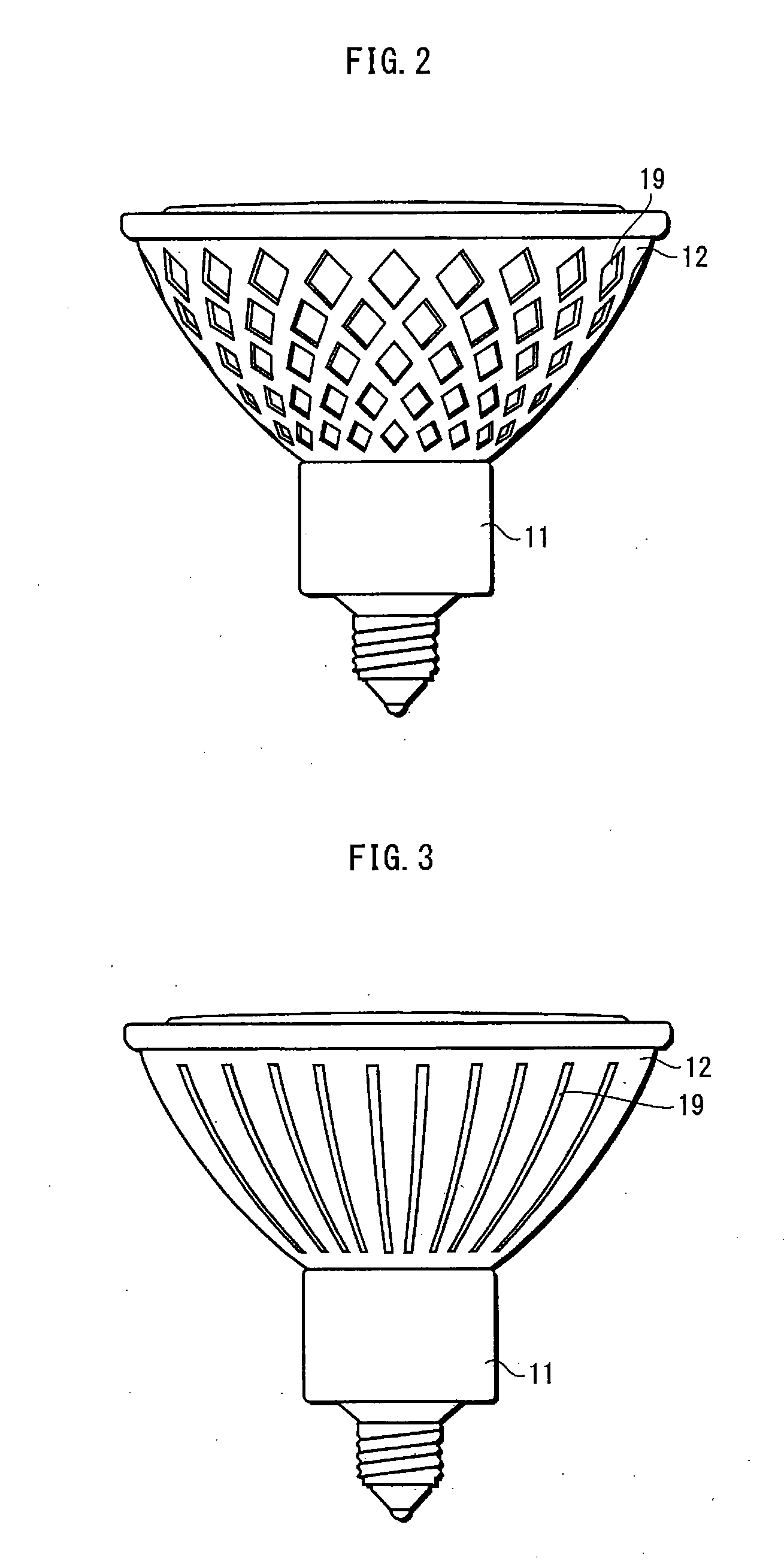
[0040]FIG. 1 is a partial cutaway view showing a structure of a lighting apparatus according to Embodiment 1 of the present invention.

[0041]A lighting apparatus 1 includes, as main components thereof, a case 11, a heat dissipator 12, and a light-emitting module 18. First, a schematic structure of each of these components is described. Then, a detailed structure of the heat dissipator 12 is described.

[0042]The case 11 is made of an insulating material such as ceramics, and is composed of a cylindrical portion 11a and a protrusion 11b. The protrusion 11b extends from an end of the cylindrical portion 11a. The cylindrical portion 11a houses therein a lighting circuit 17. A shell 15, which is made of metal, is provided on an outer circumferential surface of the protrusion 11b. An end of the protrusion 11b is provided with an eyelet 16, which is also made of metal. Both of the shell 15 and the eyelet 16 are connected to the lighting circuit 17 via wiring lines, and serve as feed terminal...

embodiment 2

[0071]FIG. 19 is a sectional view showing a structure of a lighting apparatus according to Embodiment 2 of the present invention.

[0072]A lighting apparatus 2 mainly includes the case 11, the heat dissipator 12, the light-emitting module 18, and a reflector 30. Embodiment 2 is different from Embodiment 1 in that: windows are not formed in the heat dissipator 12; the light-emitting module 18 does not include any lens; and the lighting apparatus 2 includes the reflector 30. Aside from these differences, Embodiment 2 has the same structure as Embodiment 1; therefore, descriptions thereof are omitted.

[0073]The reflector 30 is fixed inside the heat dissipator 12 with use of an adhesive agent, a screw, or the like. Since an outer circumferential surface of the reflector 30 is in contact with the inner circumferential surface of the heat dissipator 12, the mechanical strength is ensured to a certain degree even when the reflector 30 is made thinner. An opening is provided at a bottom portio...

embodiment 3

[0076]FIG. 20 is a side view showing a structure of a lighting apparatus according to Embodiment 3 of the present invention. FIG. 21 is a sectional view showing the structure of the lighting apparatus according to Embodiment 3 of the present invention. A lighting apparatus 3 according to Embodiment 3 is the same as the lighting apparatus 2 of Embodiment 2 in terms of the basic structure. The following describes differences between Embodiments 2 and 3.

[0077]In Embodiment 3, the bottom portion 12a of the heat dissipator 12 is raised, and the circumferential wall portion 12b has the windows 19. The length of the cylindrical portion 11a of the case 11, in an axis direction thereof, is shortened by the amount of the bottom portion 12a being raised.

[0078]A reflector 31 is fixed at the bottom portion 12a of the heat dissipator 12. The reflector 31 is fixed by, for example, screwing the reflector 31 into a groove provided in the bottom portion 12a or adhering the reflector 31 to the bottom ...


PUM


Abstract

Provided is a lighting apparatus that is suitable as a substitute for a conventional halogen lamp when positively utilizing leaked light. The lighting apparatus comprises: a heat dissipator 12 that is in one of a bottomed cylindrical shape and a bowl shape, and that has a bottom portion, a circumferential wall portion, and an opening; and a light-emitting device 18b that is provided inside the heat dissipator 12 at the bottom portion and is operable to emit light, wherein the heat dissipator 12 has one or more windows 19 for leaking the emitted light outside the heat dissipator 12.

Description

TECHNICAL FIELD[0001]The present invention relates to a lighting apparatus including a light-emitting device such as an LED (Light Emitting Diode).BACKGROUND ART[0002]As a lighting apparatus such as spot lighting in a commercial facility or a private residence, a reflector halogen lamp has been widely prevalent.[0003]Meanwhile, importance is placed on saving power consumption and improving life in the field of spot lighting. Accordingly, research and development are carried out on technology for substituting a lighting apparatus including an LED (hereinafter “LED lighting apparatus”) for a conventional light bulb. Reflector halogen lamps are no exceptions, and a number of reflector LED lighting apparatuses have been proposed as substitutes for such reflector halogen lamps (see Patent Literatures 1 and 2).[0004]In general, an LED produces heat when lit, and the higher the temperature of the LED is, the lower the light-emitting efficiency of the LED is. Therefore, in the practical app...

Claims


Application Information

Patent Timeline
Patent Type & Authority Applications(United States)
IPC IPC(8): H01L33/46F21V29/505
CPCF21V7/09F21V11/14F21V29/004F21Y2101/02H01L33/60F21K9/137F21V29/86H01L2924/0002F21V29/83F21V29/505F21V29/74F21V29/80H01L2924/00F21K9/233F21V5/04F21K9/69F21Y2115/10F21K9/68
Inventor KAWAGOE, SHINYAHASHIMOTO, NAOTAKAKOJIMA, TOSHIYASUIKEDA, TAKUTANIUCHI, AKIRA
Owner PANASONIC CORP
Why Eureka
Try Eureka