Electromechanical transducer device and method of forming a electromechanical transducer device

Active Publication Date: 2011-09-29
COMMISSARIAT A LENERGIE ATOMIQUE ET AUX ENERGIES ALTERNATIVES +1
View PDF15 Cites 40 Cited by
  • Summary
  • Abstract
  • Description
  • Claims
  • Application Information

AI Technical Summary

Problems solved by technology

This makes the thermal balance more difficult to be met.
In reality, however, this is complicated by manufacturing process variations.
More layers mean more processing steps and larger variations, resulting in higher cost and less reproducibility.
Also, the presence of the PZT layer before mechanical beam deposition may not be allowed due to serious contamination concerns.
In view of process constraints, it is not always possible to put the same material on both sides of the mechanical stack, due to serious contamination problems or because of process conditions.
For example, a metallic layer used as a compensation layer for a metal electrode on top of a mechanical layer and made before the mechanical layer may not be compatible with the temperature deposition of the material of the mechanical layer.
In addition to thermal stresses causing unwanted deformatio

Method used


Image

  • Electromechanical transducer device and method of forming a electromechanical transducer device
  • Electromechanical transducer device and method of forming a electromechanical transducer device
  • Electromechanical transducer device and method of forming a electromechanical transducer device

Examples


Embodiment Construction

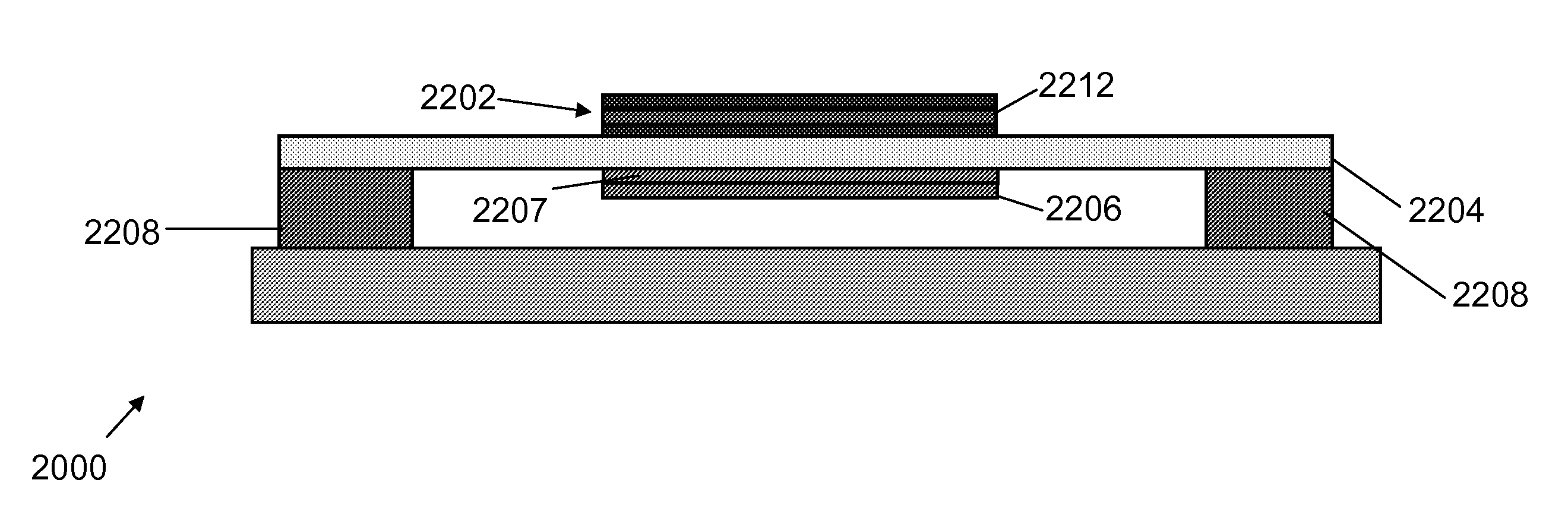
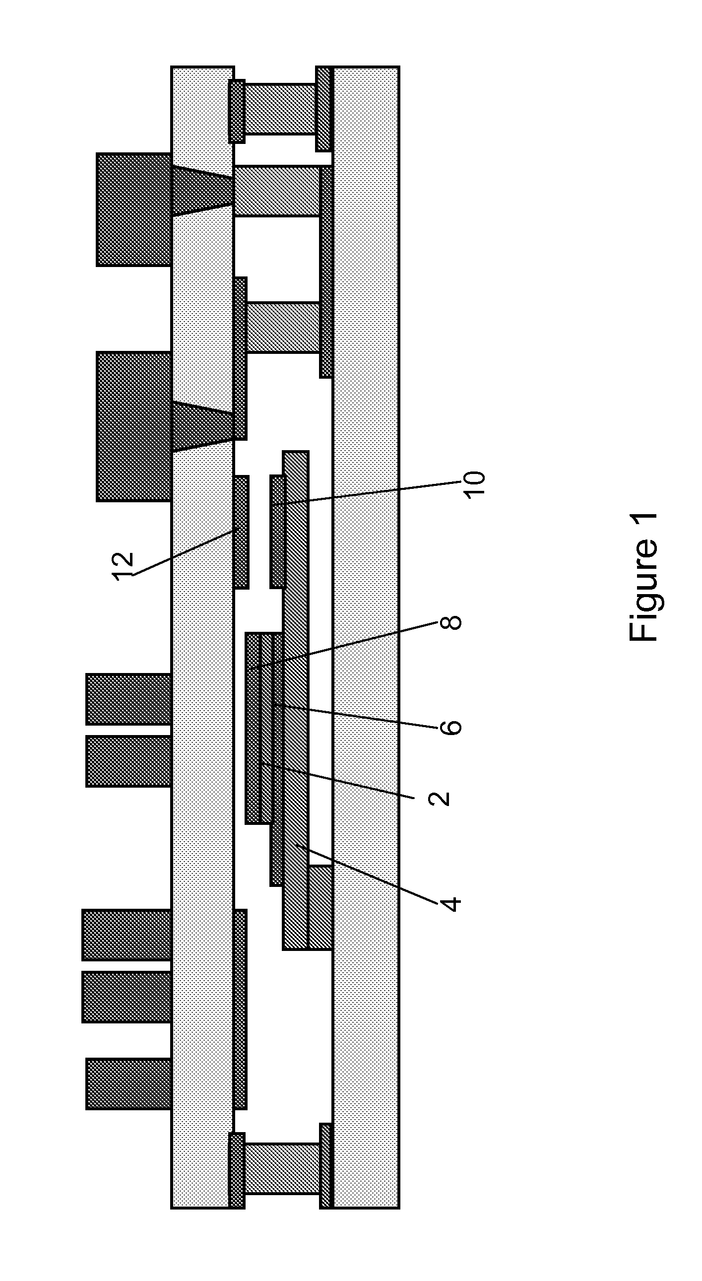
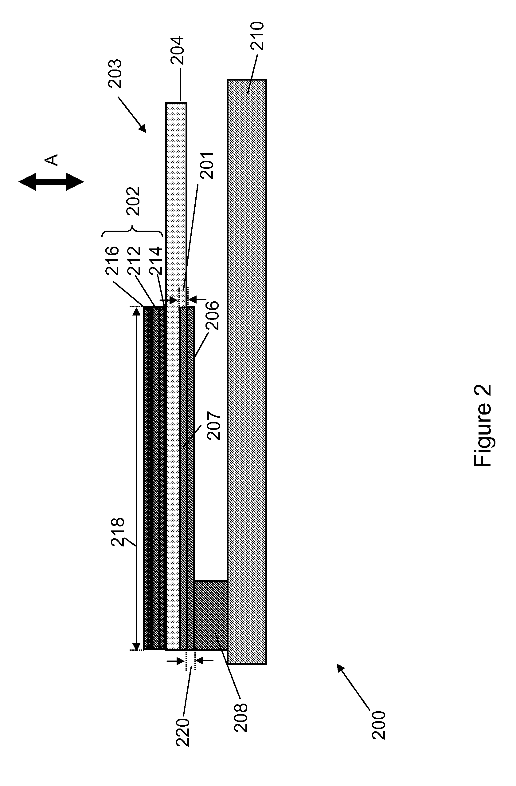
[0032]In the description that follows and in the Figures, certain regions are identified as being of a particular material, and / or type. However, this is merely for convenience of explanation and not intended to be limiting. Those of skill in the art will understand based on the description given herein that various materials can be used and that the disclosure is not limited to the particular examples given in the description.

[0033]The present disclosure will be described with reference to a piezoelectric actuated MEMS switch device. However, it will be appreciated that the disclosure is not limited to piezoelectric actuated MEMS switch devices and applies equally to other MEMS transducer devices such as sensors, actuators, accelerometers, optical switches, varactors, variable inductors, phase shifters and other means for actuation such as magnetic actuated transducer devices and electrostatic actuated MEMS devices and / or similar devices. Furthermore, the disclosure may also be use...


PUM


Abstract

A micro or nano electromechanical transducer device formed on a semiconductor substrate comprises a movable structure which is arranged to be movable in response to actuation of an actuating structure. The movable structure comprises a mechanical structure comprising at least one mechanical layer having a first thermal response characteristic and a first mechanical stress response characteristic, at least one layer of the actuating structure, the at least one layer having a second thermal response characteristic different to the first thermal response characteristic and a second mechanical stress response characteristic different to the first mechanical stress response characteristic, a first compensation layer having a third thermal response characteristic and a third mechanical stress characteristic, and a second compensation layer having a fourth thermal response characteristic and a fourth mechanical stress response characteristic. The first and second compensation layers are arranged to compensate a thermal effect produced by the different first and second thermal response characteristics of the mechanical structure and the at least one layer of the actuating structure such that movement of the movable structure is substantially independent of variations in temperature and to adjust a stress effect produced by the different first and second stress response characteristics of the mechanical structure and the at least one layer of the actuating structure such that the movable structure is deflected a predetermined amount relative to the substrate when the electromechanical transducer device is in an inactive state.

Description

FIELD OF THE INVENTION[0001]This disclosure relates to micro or nano electromechanical transducer devices and methods of forming micro or nano electromechanical transducer devices.BACKGROUND OF THE INVENTION[0002]ElectroMechanical Systems include Micro ElectroMechanical Systems (MEMS) structures and Nano ElectroMechanical systems (NEMS) and MEMS and NEMS structures are used in a wide variety of applications including, for example, MEMS accelerometers in cars for airbag deployment or in consumer electronic devices such as game controllers, MEMS gyroscopes used in cars to detect yaw, optical switching, bio -MEMS applications, MEMS loudspeakers, inkjet printers and RF MEMS components such as antenna phase shifters. Advantages of using MEMS structures include they have mechanical properties but have small dimensions and can be manufactured using existing semiconductor processing technologies.[0003]A MEMS transducer device, which may be used as an actuator or sensor, may include a movabl...

Claims


Application Information

Patent Timeline
IPC IPC(8): H01L29/84H01L21/02
CPCB81B3/0072H01L41/094H01L41/0933B81B2201/032
Inventor PERRUCHOT, FRANCOISDEFAY, EMMANUELREY, PATRICELIU, LIANJUNPACHECO, SERGIO
Owner COMMISSARIAT A LENERGIE ATOMIQUE ET AUX ENERGIES ALTERNATIVES
Why Eureka
Try Eureka