Wind turbine generator

a wind turbine generator and generator technology, applied in the direction of electric generator control, machines/engines, sliding contact bearings, etc., can solve the problems of increased costs, difficult to divide construction, and large radial direction clearances on inner ring side and outer ring side, so as to facilitate adjustment of clearances, smooth operation, and reduce the effect of shaft center shifting

Inactive Publication Date: 2011-09-29
MITSUBISHI HEAVY IND LTD
View PDF13 Cites 27 Cited by
  • Summary
  • Abstract
  • Description
  • Claims
  • Application Information

AI Technical Summary

Benefits of technology

[0023]In this case, it is preferable that the roller follower be provided with a clearance-adjusting mechanism; accordingly, manufacturing tolerances for the clearances can be set loosely during manufacturing at a factory, and the clearances can eventually be adjusted at a construction site. In addition, it is also possible to easily adjust the clearances in portions that are partially replaced at a construction site when the yawing sliding bearing is damaged.
[0024]With the above-described invention, in the yawing sliding bearing, the flange preferably has T-shape forming top and bottom support surfaces on an inner circumferential side and an outer circumferential side of the stationary portion, and it is preferable that the rolling element be provided on at least one of the inner circumferential side and the outer circumferen

Problems solved by technology

That is because a yawing ring bearing having a large diameter becomes necessary with the size enlargement of a wind turbine generator, the roller bearing 12, which makes it difficult to have a divided construction, has problems of increased costs from having to make the ball bearing 12c, etc. as custom-made parts, land

Method used


Image

  • Wind turbine generator
  • Wind turbine generator
  • Wind turbine generator

Examples


first embodiment

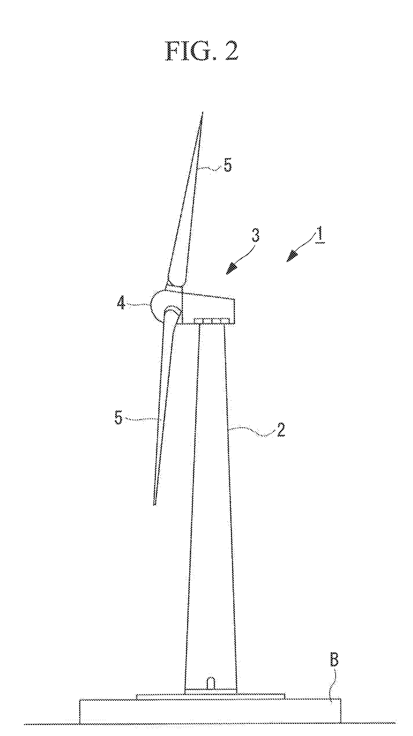
[0064]The above-described wind turbine generator 1 is provided with a yawing device 10A that is installed at the top end of the tower 2 for turning the nacelle 3 in order to match the orientation of the rotor head 4 with the constantly changing wind direction.

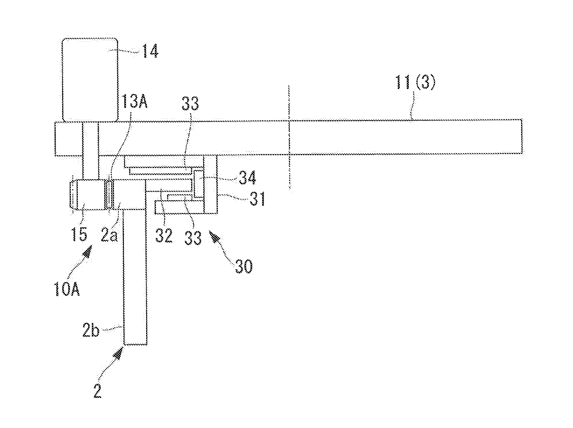
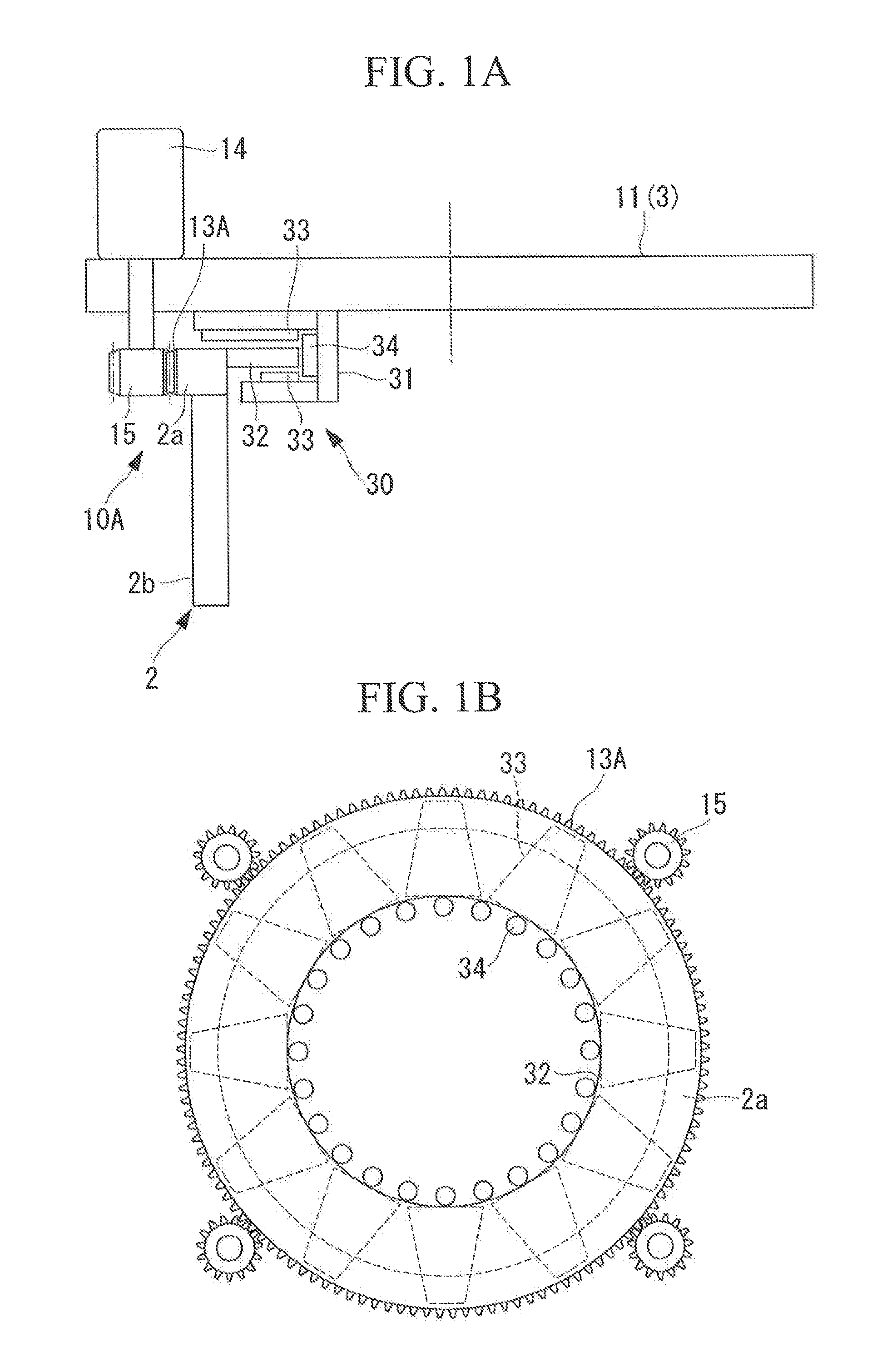
[0065]This yawing device 10A is provided with a yawing sliding bearing 30 that mainly bears a moment load at flat portions thereof in order to turnably support the nacelle 3 installed at the top end of the tower 2.

[0066]The illustrated yawing sliding bearing 30 is configured such that horizontal sliding bearing members (hereinafter referred to as “horizontal bearing members”) 33 and rolling elements 34 are interposed between a turning portion 31 secured to a base member (nacelle base plate) 11 on the nacelle 3 side, which turns at the top end of the tower 2, and a stationary portion 32 that are secured on the tower 2 side, which is stationary.

[0067]The turning portion 31 is a ring member having an angular U-shaped cross-section...

second embodiment

[0077]Next, a second embodiment of the wind turbine generator according to the present invention will be described on the basis of FIGS. 3A to 6B. Note that the same reference signs are given to the same components as those in the above-described embodiment, and detailed descriptions thereof will be omitted.

[0078]In this embodiment, roller followers 40 are employed as the above-described rolling elements 34. A yawing sliding bearing 30A employs turning bearing units 31A that are divided into multiple portions in the circumferential direction of the turning portion 31, as shown in FIGS. 3B and 4, for example. That is, the yawing sliding hearing 30A of this embodiment is configured such that a plurality of the turning-bearing units 31A are disposed in the circumferential direction at equal pitch instead. of disposing the turning portion 31 over the entire circumference.

[0079]The roller followers 40 form sliding surfaces, as shown in FIGS. 3A and 3C for example, wherein cylinders 41 co...

third embodiment

[0092]Next, a third embodiment of the wind turbine generator according to the present invention will be described on the basis of FIG. 7. Note that the same reference signs are given to the same components as those in the above-described embodiment, and detailed descriptions thereof will be omitted.

[0093]In this embodiment, a turning portion 31A of a yawing sliding bearing 30B has an integrated structure in which a pair of top and bottom rings 35 and 36 are connected.

[0094]With the pair of too and bottom rings 35 and 36, the ring 35, which has a substantially L-shaped cross-section and which is disposed at the top portion, is connected to the ring 36, which has a substantially rectangular cross-section and which is disposed at the bottom portion, thereby forming, as a whole, a ring member of the turning portion 31B having a substantially angular U-shaped cross-section. In addition, when integrating the top and bottom ring members 35 and 36, the rolling elements 34 are installed so a...


PUM


Abstract

A wind turbine generator provided with a sliding bearing as a yawing ring bearing that can reduce shifting of an axial center by making radial-direction clearances small. In a wind turbine generator in which a nacelle installed at the top of a tower is turnably supported via a yawing sliding bearing, the yawing sliding bearing is provided with a sliding member 33 disposed between top and bottom support surfaces of a flange formed mainly at a stationary portion and a turning portion; and a rolling element disposed between the stationary portion of the yawing sliding hearing and the turning portion.

Description

TECHNICAL FIELD[0001]The present invention relates to a wind turbine generator in which power is generated by a generator driven by a main shaft that rotates by receiving wind force, and it relates, in particular, to a structure of a sliding bearing employed in a yawing (YAW) ring bearing structure of a wind turbine generator.BACKGROUND ART[0002]A wind turbine generator is a device in which a rotor head provided with turbine blades rotates by receiving wind force, and this rotation is sped up by a gearbox to drive a generator, thereby generating power. In addition, because the gearbox and the generator inside a nacelle installed at a top portion of a tower are connected, in order to match the orientation of the rotor head with the constantly changing wind direction, a yawing device for turning the nacelle on the tower is required.[0003]FIG. 9 shows an example configuration of a conventional yawing device.[0004]In a yawing device 10 shown in FIG. 9, a roller bearing 12 is employed, i...

Claims


Application Information

Patent Timeline
IPC IPC(8): F03D9/00
CPCF03D11/0008F16C17/04F16C19/26F16C19/507Y02E10/726F16C21/00Y02E10/722F03D80/70F16C2300/14F16C2360/31F16C25/06Y02E10/72F05B2240/50
Inventor NODA, YOSHITOMONUMAJIRI, TOMOHIROSEKI, SEITA
Owner MITSUBISHI HEAVY IND LTD
Why Eureka
Try Eureka