
Display device, image signal correction system, and image signal correction method

a technology of image signal and display device, applied in the field of display device, image signal correction system, image signal correction method, can solve the problems of memory size and product cost increase, decrease yield, etc., and achieve the effects of improving yield, enhancing uniformity, and improving image quality

Inactive Publication Date: 2011-09-29
SAMSUNG DISPLAY CO LTD
View PDF22 Cites 68 Cited by
  • Summary
  • Abstract
  • Description
  • Claims
  • Application Information

AI Technical Summary

Benefits of technology

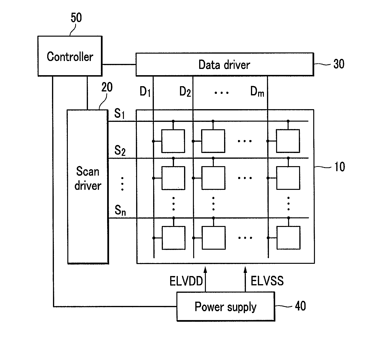
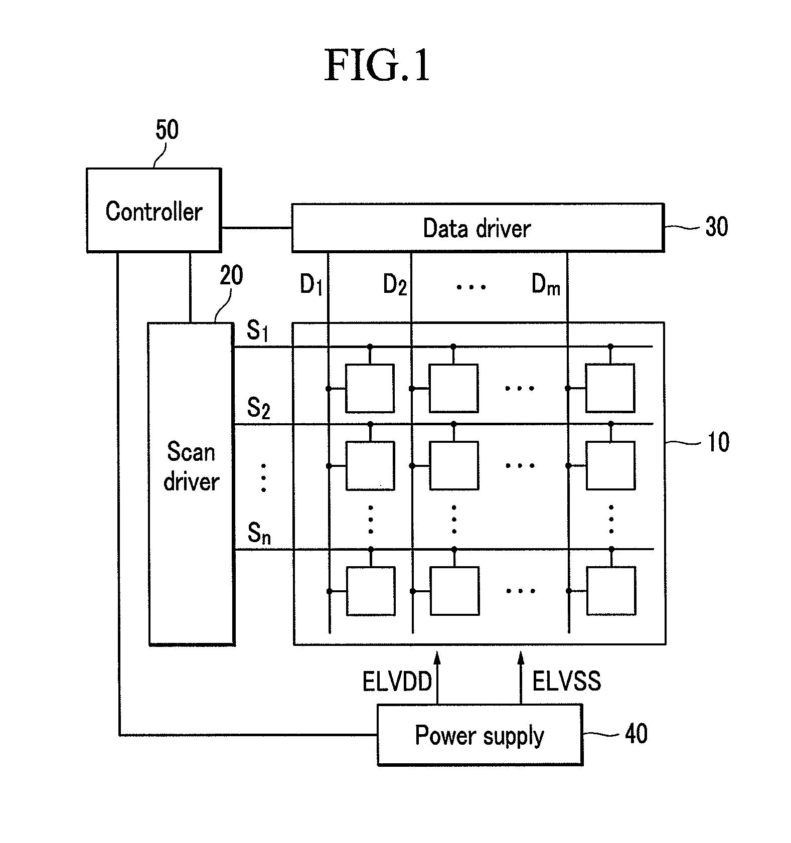
[0010]It is therefore a feature of an embodiment to provide a device that improves image quality by enhancing uniformity through measurement and correction of luminance and color of light emitted from a larger display device, and a method thereof.
[0011]It is another feature of an embodiment to provide a display device using an image signal correction system that can compensate for non-uniformity of a thin film transistor in a pixel of the display device.
[0012]It is yet another feature of an embodiment to provide a large display device that can be mass produced and that addresses power IR drop, OLED cavity non-uniformity, and loading effect.
[0013]It is still another feature of an embodiment to provide an image signal correction method for mass production of a display device with improved yield and reduced production cost, while also providing a display device which compensates for pixel non-uniformity, e.g., in mid-sized or large display panels, using a minimal amount of memory to provide a display device of which image quality is improved through correction of wavelength shift that occurs according to a location on the display panel.

Problems solved by technology

However, when a conventional correction method is used to solve the problems, the memory size and product cost may increase while decreasing the yield.

Method used


Image

  • Display device, image signal correction system, and image signal correction method
  • Display device, image signal correction system, and image signal correction method
  • Display device, image signal correction system, and image signal correction method

Examples


Embodiment Construction

[0046]Korean Patent Application No. 10-2010-0026853, filed on Mar. 25, 2010, in the Korean Intellectual Property Office, and entitled: “Display Device, Image Signal Correction System, and Image Signal Correction Method,” is incorporated by reference herein in its entirety.

[0047]Example embodiments will now be described more fully hereinafter with reference to the accompanying drawings; however, they may be embodied in different forms and should not be construed as limited to the embodiments set forth herein. Rather, these embodiments are provided so that this disclosure will be thorough and complete, and will fully convey the scope of the invention to those skilled in the art.

[0048]Constituent elements having the same structures throughout the embodiments are denoted by the same reference numerals and are described in a first exemplary embodiment. In the subsequent exemplary embodiments, only the constituent elements other than the same constituent elements are described.

[0049]The d...


PUM


Abstract

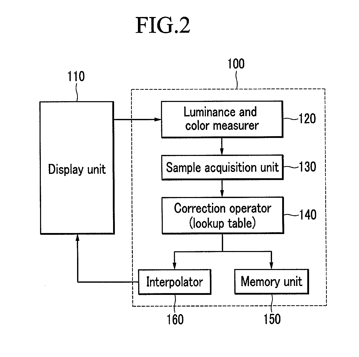
A display device includes a display unit and a controller, the controller generating and transmitting a scan signal and an image data signal to a scan driver and a data driver, respectively. The controller includes a memory unit storing a look-up table of basic correction amounts for a test image data signal according a comparison result of comparing a measured value of an image of the display unit displaying the test image data signal with a target value of the test image data signal, and a data controller storing data for a modulation coefficient for applying the look-up table to the supplied image data signal, calculating a full correction amount corresponding to the supplied image data signal using the modulation coefficient and the basic correction amount of the look-up table, and outputting a corrected image data signal by correcting the supplied image data signal by the full correction amount.

Description

BACKGROUND[0001]1. Field of the Invention[0002]Embodiments relate to a display device, an image signal correction system, and an image signal correction method.[0003]2. Description of the Related Art[0004]Various kinds of flat display devices that are capable of reducing the weight and size of cathode ray tubes (CRT) have been developed in recent years. Such flat display devices include liquid crystal displays (LCDs), field emission displays (FEDs), plasma display panels (PDPs), and organic electroluminescence display devices.[0005]Among the flat panel displays, OLED display displays an image by using an OLED that generates light according to recombination of electrons and holes. The OLED display receives much attention due to its fast response speed, low power consumption, high luminance, and wide viewing angle. Further, the OLED display has excellent color reproducibility and can be slim, so it can be applied to various markets including mobile phones, PDAs, MP3 Players, TVs, and ...

Claims


Application Information

Patent Timeline
IPC IPC(8): G09G5/10
CPCG09G3/2003G09G5/10G09G2320/0233G09G3/3208G09G2320/0285G09G2320/0693G09G2360/145G09G2320/0242
Inventor PARK, KYONG-TAEARKHIPOV, ALEXANDERLEE, BAEK-WOONKIM, SEON-MIN
Owner SAMSUNG DISPLAY CO LTD
Learn More