Scanning-type distance measuring apparatus

a distance measuring and scanning type technology, applied in the direction of distance measurement, instruments, using reradiation, etc., can solve the problems of inability to ensure reliability and difficulty in miniaturizing the apparatus

Active Publication Date: 2011-09-29
HOKUYO AUTOMATIC CO
View PDF3 Cites 57 Cited by
  • Summary
  • Abstract
  • Description
  • Claims
  • Application Information

AI Technical Summary

Benefits of technology

[0013]In view of the above problem, it is an object of the present invention to provide an inexpensive scanning-type distance measuring apparatus realizing miniaturization and easy detection that an optical window is purposely or carelessly covered with a light shield sheet or the like.
[0015]With the configuration, the measurement light deflected by the first deflecting member is output from the incident light path of the reflection light to the second deflecting member. Consequently, even in a case where a light shield sheet or the like is made to adhere to the optical window, a part of the reflection light from the light shield sheet or the like enters the second deflecting member along the incident light path. On the basis of such measurement light and reflection light, existence of a foreign matter such as the light shield sheet in a close range can be reliably detected.
[0016]Preferably, a region through which the measurement light passes in the light receiving lens is notched. Since the measurement light deflected by the first deflecting member passes through the notched region in the light receiving lens, the measurement light can be properly output toward the space to be measured without being refracted by the light receiving lens.
[0017]Preferably, the optical member is configured by the second deflecting member and the first deflecting member whose deflecting face is extended to a part of a region along the scanning direction in the deflecting face of the second deflecting member. When measurement light output from the region extended to the second deflecting member in the deflecting face of the first deflecting member to the space to be measured is reflected by a foreign matter such as a light shield sheet, a part of the reflection light is incident on a region adjacent to the extended region along the scanning direction in the deflecting face of the second deflecting member. Consequently, the existence of a foreign matter such as a light shield sheet can be reliably detected.
[0018]Preferably, the first and second deflecting members are integrally formed. By integrally forming the optical member such that the angle formed by the deflecting face of the first deflecting member and the deflecting face of the second deflecting member is a predetermined angle, it becomes unnecessary to adjust the incidence angle and the reflection angle at the deflecting faces of the measurement light and the reflection light. The scanning-type distance measuring apparatus can be easily and precisely assembled with the smaller number of parts.
[0022]Preferably, the third deflecting member is disposed in the notch in the light receiving lens. Since the measurement light deflected by the first deflecting member passes through the third deflecting member disposed in the notch in the light receiving lens, the measurement light can be properly output toward the space to be measured without being refracted by the light receiving lens.

Problems solved by technology

There is a problem of difficulty in miniaturization of the apparatus.
In a case where a light shield sheet or the like is made to adhere to a transparent window purposely or carelessly, the following problem occurs.
Consequently, when the scanning-type distance measuring apparatus is used in a monitor sensor or the like, the reliability cannot be assured.

Method used


Image

  • Scanning-type distance measuring apparatus
  • Scanning-type distance measuring apparatus
  • Scanning-type distance measuring apparatus

Examples


first embodiment

[0037]A scanning-type distance measuring apparatus according to the present invention is described below.

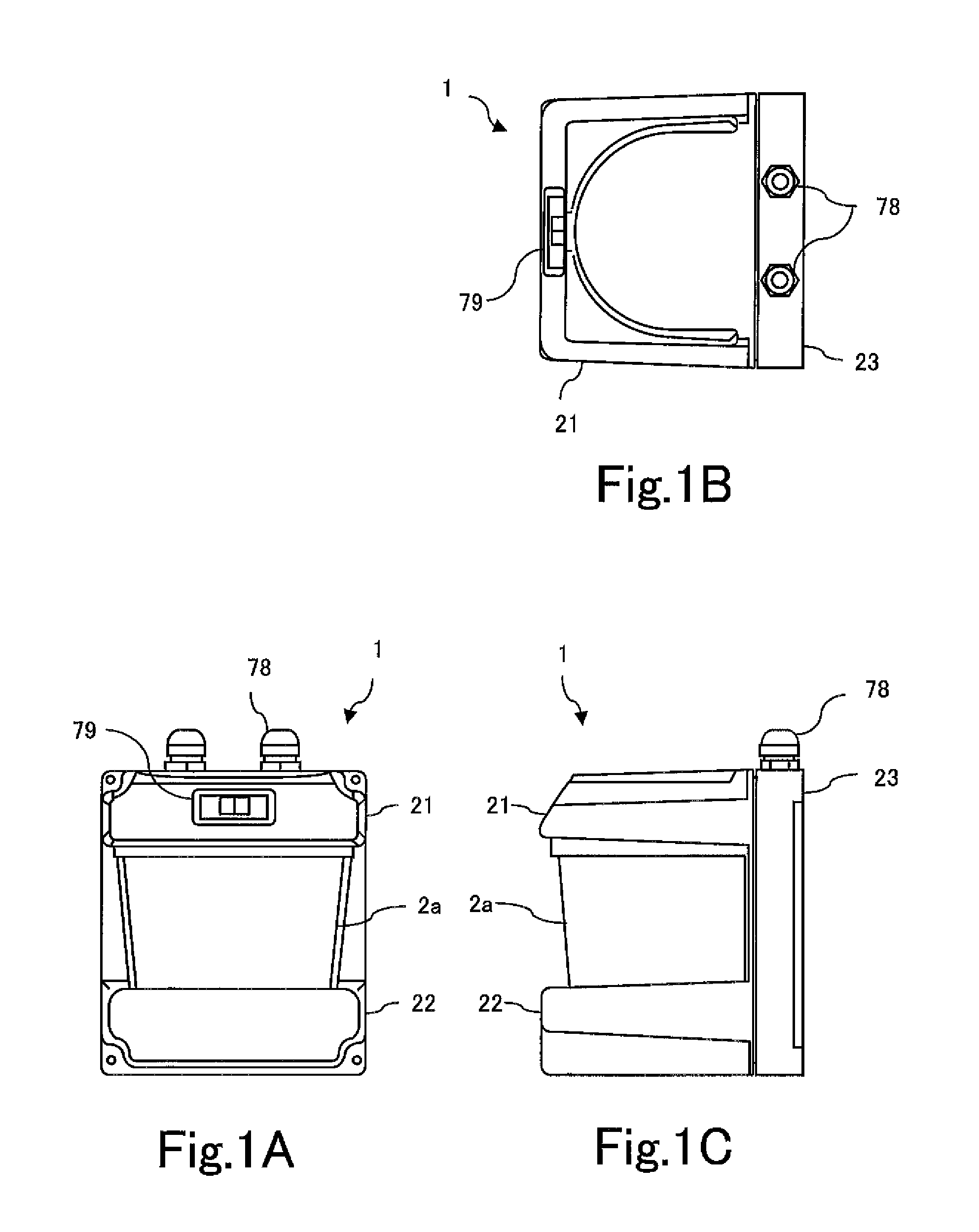
[0038]As shown in FIGS. 1A to 1C, in a scanning-type distance measuring apparatus 1 according to the present invention, a light-transmissive optical window 2a formed in a curved plane having an almost semicircular shape in cross section is disposed between an upper housing 21 and a lower housing 22, and a monitor display unit 79 by which the state of the apparatus 1 can be determined is provided on the front face of the upper housing 21.

[0039]To the top face of a rear housing 23 disposed so as to oppose the optical window 2a, a pair of cable clamps 78 for connecting signal cables for taking distance information detected by the scanning-type distance measuring apparatus 1 to the outside are attached.

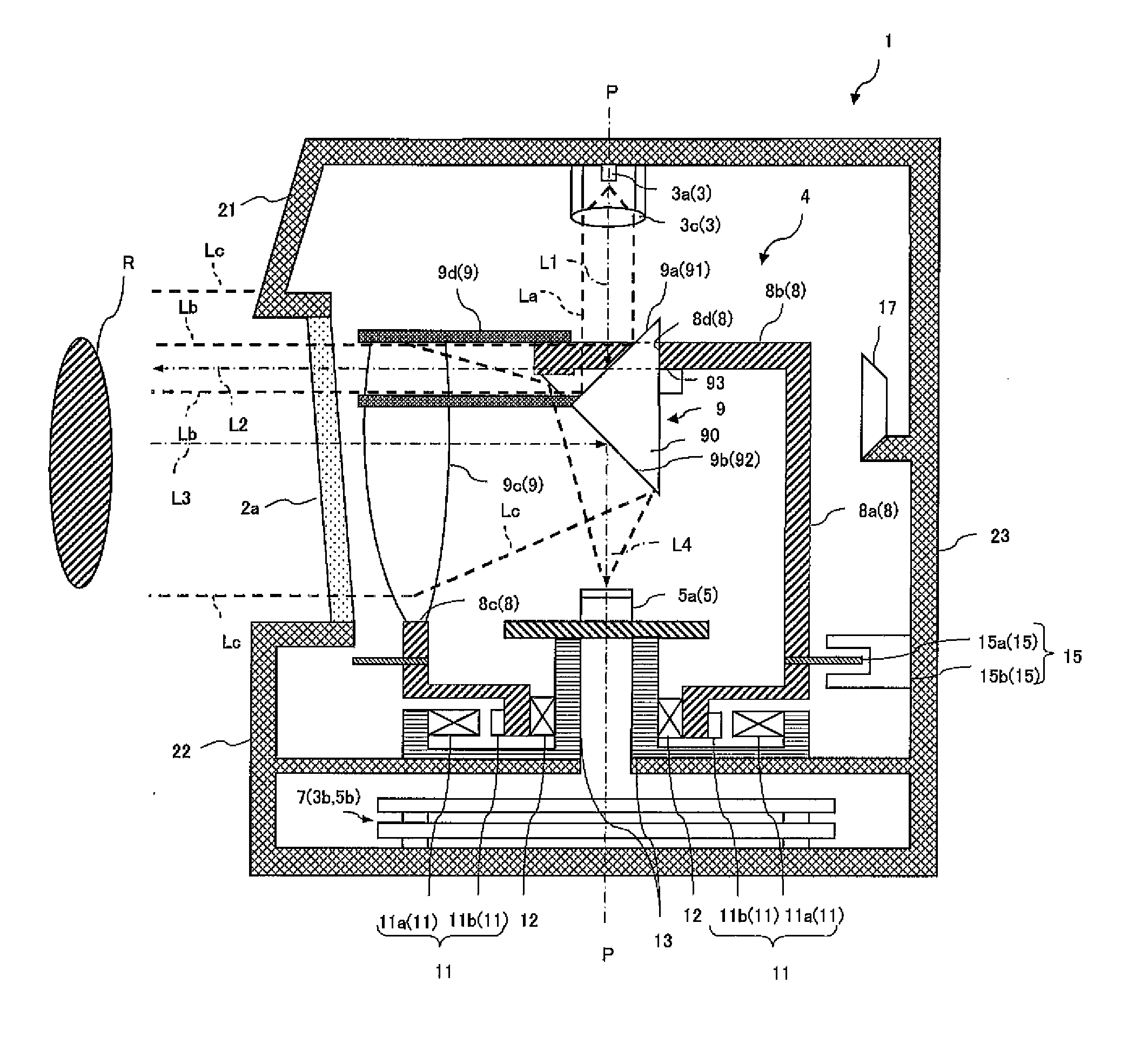
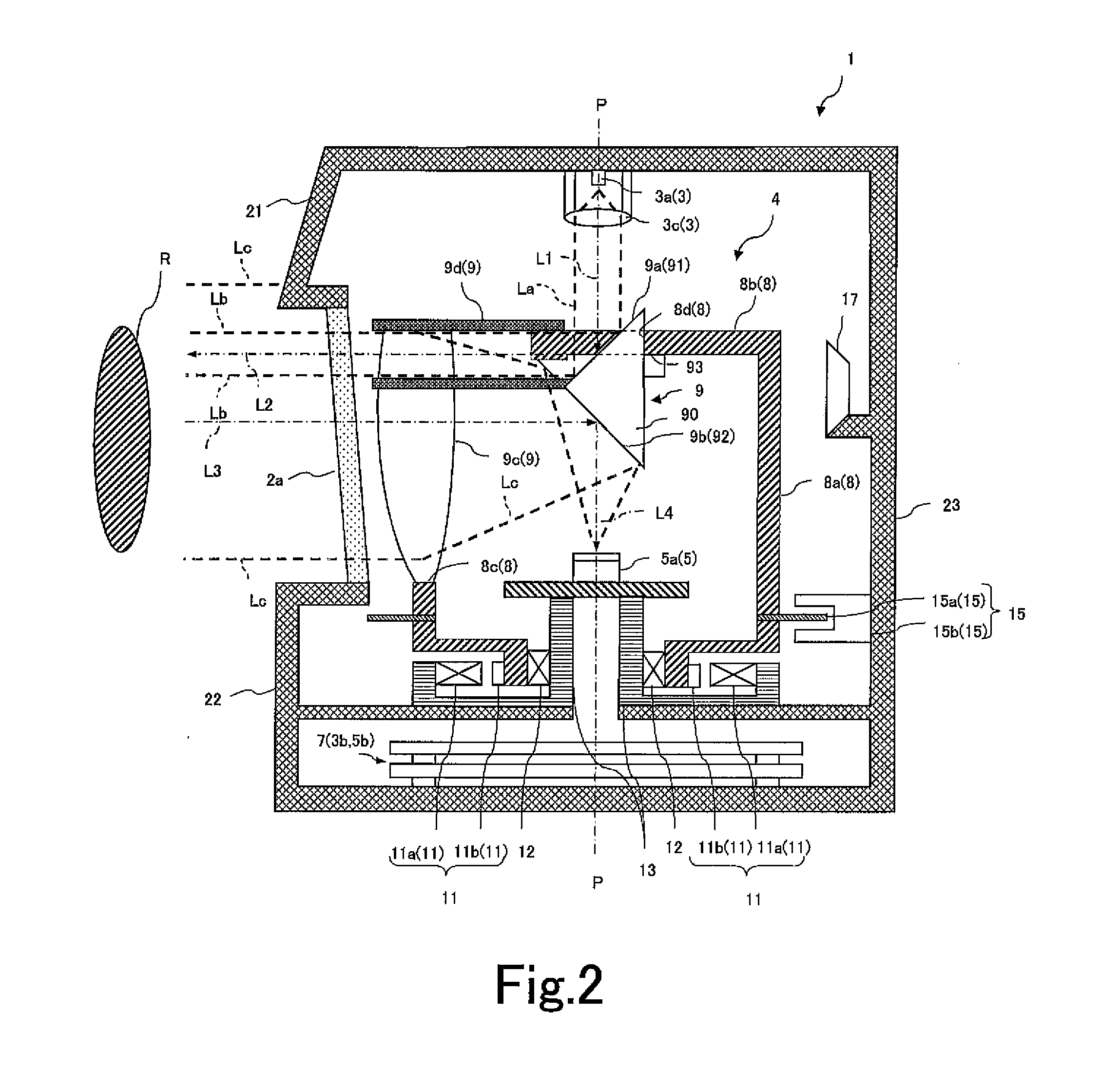
[0040]As shown in FIGS. 11A and 11B, the scanning-type distance measuring apparatus 1 modulates measurement light output from a light source LD such as a laser, irradiates an object R ...

second embodiment

[0073]Next described is a scanning-type distance measuring apparatus according to the present invention.

[0074]The second embodiment is different from the first embodiment described above in the configuration of the optical member 90. In the following, the configuration of the optical member 90 making a difference will be mainly described. The same reference signs are denoted to the common components and detailed description thereof will not be repeated.

[0075]As shown in FIGS. 6 and 7, to the rotator 8 incorporated in a scanning-type distance measuring apparatus 10, the optical system 9 is attached. The optical system 9 includes: the first deflecting mirror 9a as a first deflecting member that deflects, by 90 degrees toward the space to be measured, measurement light output along the optical axis L1 from the light transmitting unit 3; the light receiving lens 9c that condenses reflection light from the object R to be measured existing in the space to be measured; and the second defle...


PUM


Abstract

A scanning-type distance measuring apparatus includes: an optical system 9 having a first deflecting member 9a that deflects measurement light output from a light transmitting unit 3 toward a space to be measured via an optical window, a light receiving lens 9c that condenses reflection light from an object R to be measured existing in the space to be measured, and a second deflecting member 9b that deflects the reflection light passed through the light receiving lens toward a light receiving unit 5 disposed to oppose the light transmitting unit 3; a scanning mechanism 4 that rotates the optical system 9 about a predetermined axis P; and an optical member 90 that outputs the measurement light deflected by the first deflecting member 9a from an incident light path Lc of the reflection light to the second deflecting member 9b.

Description

BACKGROUND OF THE INVENTION[0001]1. Field of the Invention[0002]The present invention relates to a scanning-type distance measuring apparatus for scanning a space to be measured with measurement light and measuring a distance to an object to be measured on the basis of the measurement light and reflection light from the object to be measured existing in the space to be measured.[0003]2. Description of the Related Art[0004]A scanning-type distance measuring apparatus of this kind is used in a navigation sensor as a visual recognition sensor for a robot or an unmanned vehicle, a door open / close sensor, a safety sensor for detecting a person or matter approaching a dangerous machine and safely stopping the machine, an ETC system sensor for detecting the shape of a car, determining the type of the car, and counting the number of cars passing, a traffic sensor for detecting people, counting the number of people, and detecting traffic and the flow of people, a monitor sensor for detecting...

Claims


Application Information

Patent Timeline
Patent Type & Authority Applications(United States)
IPC IPC(8): G01C3/08
CPCG01C3/08G01S7/4813G01S17/42G01S7/497G01S17/08G01S7/4817
Inventor MORI, TOSHIHIROTSUKUDA, SHINICHI
Owner HOKUYO AUTOMATIC CO
Why Eureka
Try Eureka