Control device, laser projection device, recording method, computer program, and recording medium

a laser projection and control device technology, applied in the direction of instruments, printing, electrical appliances, etc., can solve the problems of excessive heat, incomplete erasure of characters or images, and a decrease in the service life of media

Inactive Publication Date: 2011-09-29
RICOH KK
View PDF16 Cites 8 Cited by
  • Summary
  • Abstract
  • Description
  • Claims
  • Application Information

AI Technical Summary

Benefits of technology

[0016]Accordingly, embodiments of the present invention may provide a novel and useful control device, a laser projection device including the control device, a recording method, a computer program product for executing the recording method, and a storage medium containing the computer program solving one or more of the problems discussed above. More specifically, the embodiments of the present invention may provide a control device that is c

Problems solved by technology

However, when excessive heat is applied to the thermal rewritable media, the properties may be altered to cause degradation, such as a decrease in service life-span of the media or incomplete erasure of characters or images from the media.
Some portions of the medium may, when recording a certain image on the medium, easily acquire the excessive heat.
In this case, the structure of the molecules of the thermal rewritable medium may be damaged due to thermal denaturation, thereby exhibiting an adverse effect on the thermal rewritable medium, such as inability to erase recorded matter.
However, Japanese Laid-Open Patent Application No. 2008-208631 does not disclose a technology to eliminate thermal overlaps between the two parallel strokes.
It is difficult to control the scanning positions without creating thermally overlapped regions of the lines I and II and to display colors without creating any gaps between the lines I and II.
However, similar to the case of controlling the scanning positi

Method used


Image

  • Control device, laser projection device, recording method, computer program, and recording medium
  • Control device, laser projection device, recording method, computer program, and recording medium
  • Control device, laser projection device, recording method, computer program, and recording medium

Examples


first embodiment

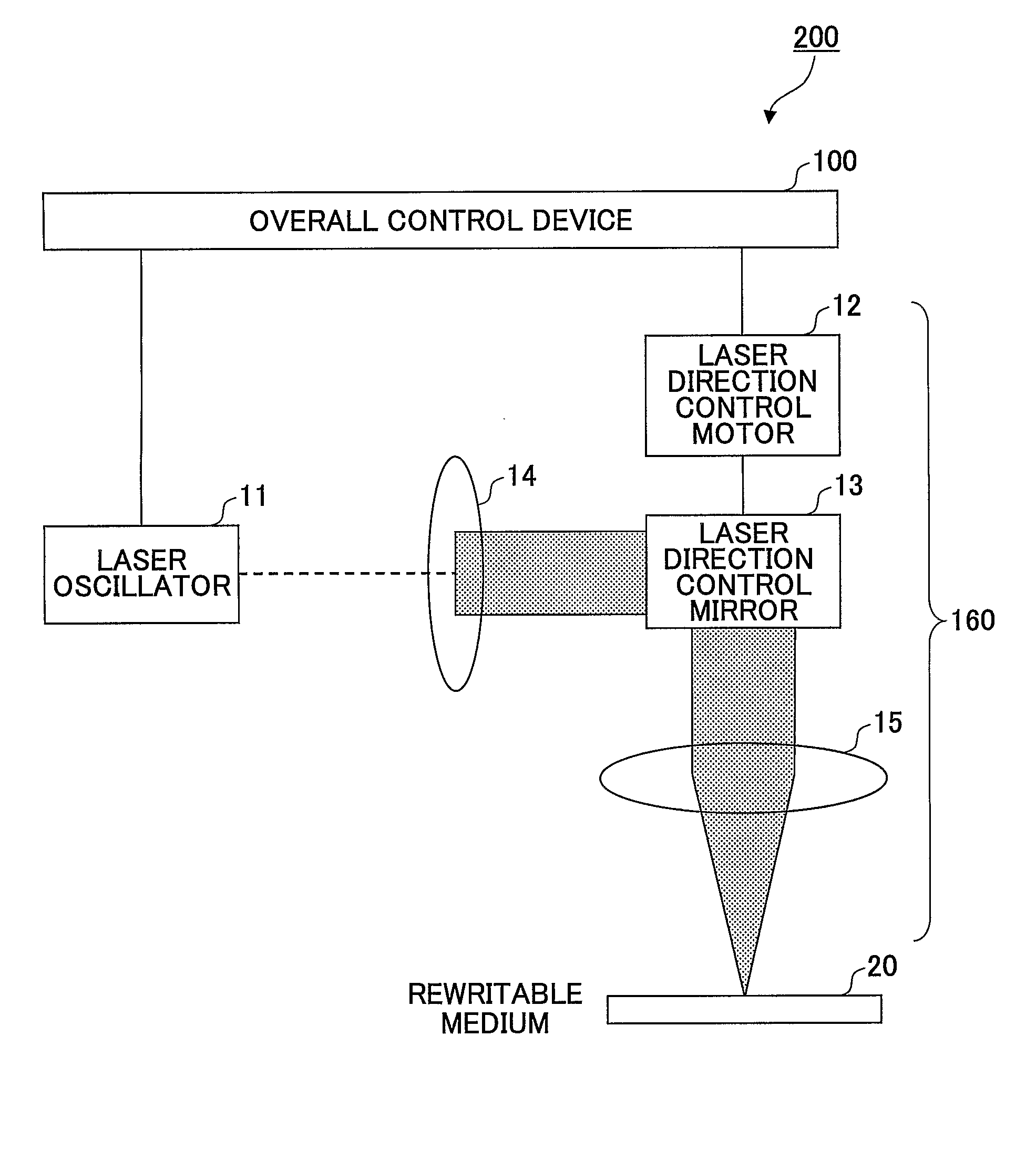
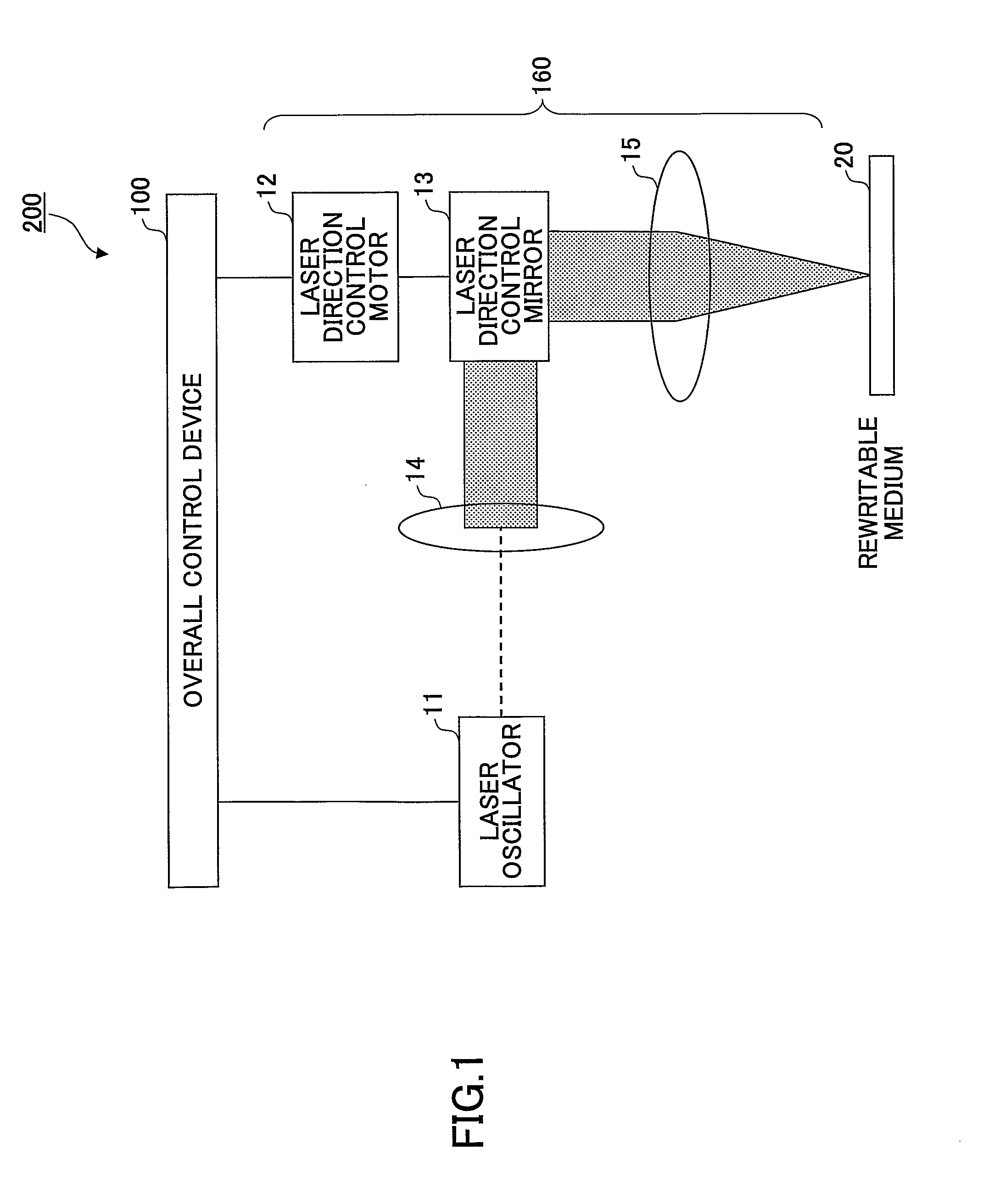
[0052]In this embodiment, the laser projection device 200 scanning a stroke by the method A is described. First, a hardware configuration of the laser projection device 200 is described. FIG. 1 illustrates an example of a hardware configuration of the laser projection device 200 according to the embodiment. Note that the hardware configuration of the laser projection device 200 is the same in all the following embodiments.

[0053]The laser projection device 200 includes an overall control device 100 that controls overall operations of the laser projection device 200, and a laser projection section 160 that projects a laser beam. The laser projection section 160 also includes a laser oscillator 11 that generates a laser beam, a laser direction control mirror 13 that controls a direction of the generated laser beam, a laser direction control motor 12 that controls the laser direction control mirror 13, an optical lens 14, and a converging lens 15.

[0054]The laser oscillator 11 in this em...

second embodiment

[0129]In this embodiment, the laser projection device 200 that scans a stroke by the method B is described. That is, the plotting instruction includes a waiting time wb, in which no residual heat interference is generated from “the scanning end time of a preceding stroke” to “the scanning start time of a subsequent stroke”.

[0130]In the first embodiment, the scanning directions are uniform and the plotting time for plotting one graphic may be minimized, accordingly. However, in a case where a character or symbol is not required to be solidly shaded; that is, the strokes configure an outline of a character, symbol, or graphic, it may be more effective to immediately start scanning after moving the laser projection position from the scanning endpoint of the preceding stroke to the scanning start point of the subsequent stroke without having the waiting time wa of the plotting method A.

[0131]In the method B, the plotting instruction includes a waiting time wb, in which no residual heat ...

third embodiment

[0169]The first embodiment illustrates a method in which an enclosed region is plotted by being solidly shaded whereas the second embodiment illustrates a method in which a character, symbol, or number is plotted by combining the strokes. Note that a graphic may be solidly shaded by setting the waiting time wb described in the second embodiment; however, the plotting time may increase if the scanning direction is not constant due to an increase of the waiting time wb. Accordingly, it is preferable that the plotting method A or B be selectable based a subject to be plotted (hereafter also called “plotting subject”) such as a character, symbol, number, or graphic on the rewritable medium 20. The third embodiment describes a laser projection device 200 that can select one of the plotting methods A and B based on the plotting subject.

[0170]FIG. 19 illustrates an example of functional components of the laser projection device 200 according to the third embodiment. Note that in FIG. 19, c...


PUM


Abstract

A control device includes a shape information storage storing shape information to be plotted, a stroke generation unit generating first and second stroke data having transmission start and end coordinates of first and second strokes, a scanning start time computation unit determining scanning start time of the second stroke by adjusting, when selecting first and second points having a shortest distance, a waiting time to scan the second stroke, a traveling rate from the transmission end coordinates of the first stroke to the transmission start coordinates of the second stroke, and scanning rates of scanning the first and second strokes to have a desired time interval between the selected points, a plotting instruction generation unit generating plotting instructions including the scanning start time of the second stroke and the transmission start and end coordinates of the first and second strokes, a plotting instruction storage storing the plotting instructions, and a plotting instruction execution unit executing the plotting instructions.

Description

TECHNICAL FIELD[0001]The present invention generally relates to a control device for controlling a plotting device that plots line images such as characters or raster images in a contact or non-contact manner. More specifically, the present invention relates to a control device for controlling a plotting device capable of reducing an amount of damage on a surface of a recording material even if information is repeatedly recorded on or erased from the surface of the recording material, a laser projection device including the control device, a recording method for reducing the amount of damage on a surface of a recording material, a computer program product for executing the recording method, and a recording medium containing the computer program.BACKGROUND ART[0002]Laser projection devices (laser markers) that thermally mark characters and symbols on materials are commercially available. Specifically, such laser projection devices generally incorporate a technology in which a materia...

Claims


Application Information

Patent Timeline
IPC IPC(8): H04N1/04
CPCB41J2/32B41J2/4753B41J2/36G02B26/10
Inventor HASEGAWA, FUMIHIROISHIMI, TOMOMI
Owner RICOH KK
Why Eureka
Try Eureka