Light emitting diode assembly

a technology of light-emitting diodes and assembly parts, which is applied in the direction of light-emitting devices, semiconductor devices for light sources, solid-state devices, etc., can solve the problems of difficult to achieve desired white light, relatively poor color rendering index of light-emitting diodes, and relatively high color temperature, so as to prevent the shift of light spectrum, suppress thermal interference, and prevent the effect of color coordinate change over tim

Active Publication Date: 2015-12-01
SEOUL SEMICONDUCTOR
View PDF8 Cites 4 Cited by
  • Summary
  • Abstract
  • Description
  • Claims
  • Application Information

AI Technical Summary

Benefits of technology

[0008]Exemplary embodiments of the present invention provide a light emitting diode assembly capable of preventing spectrum shift of a red light emitting diode chip.
[0009]Exemplary embodiments of the present invention also provide a light emitting diode assembly capable of reducing thermal interference between a red light emitting diode chip and other light emitting diode chips emitting light of different wavelengths.

Problems solved by technology

However, since the combination of the blue light emitting diode and the yellow phosphor provides white light showing a lack of red emission, a light emitting diode assembly based on this combination has relatively poor color rendering index and relatively high color temperature.
Thus, even in the case where the light emitting diode assembly realizes white light in desired color coordinates in initial operation, the color coordinates change over time, making it difficult to realize desired white light.

Method used


Image

  • Light emitting diode assembly
  • Light emitting diode assembly
  • Light emitting diode assembly

Examples


Embodiment Construction

[0043]Embodiments of the present invention will be described in more detail with reference to the accompanying drawings. It should be understood that the following embodiments are given by way of illustration only to provide thorough understanding of the invention to those skilled in the art. Therefore, the present invention is not limited to the following embodiments and may be embodied in different ways. Further, like components will be denoted by like reference numerals throughout the specification, and the widths, lengths, and thicknesses of certain elements, layers or features may be exaggerated for clarity.

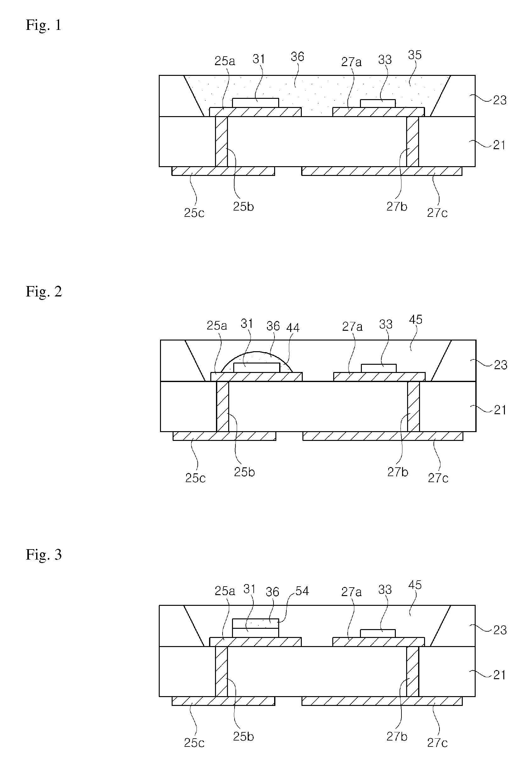
[0044]FIG. 1 is a schematic sectional view of a light emitting diode assembly according to one embodiment of the present invention.

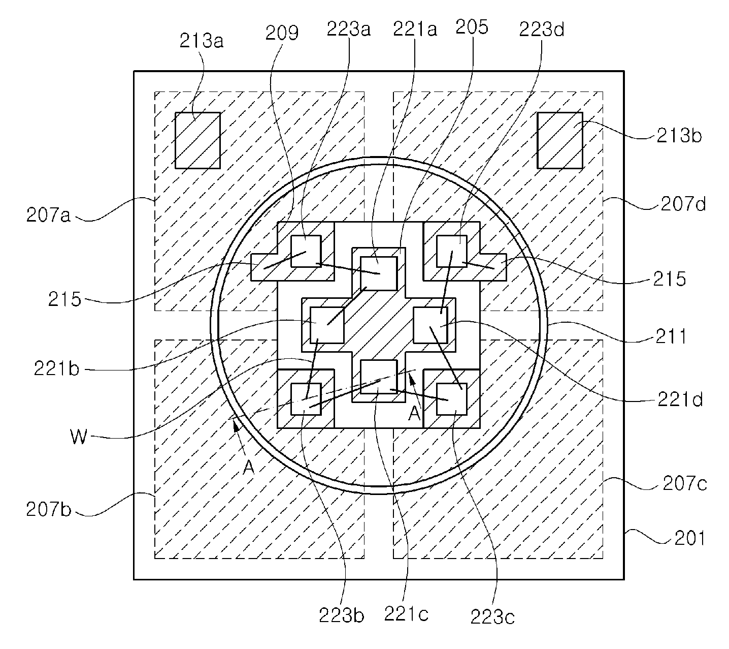
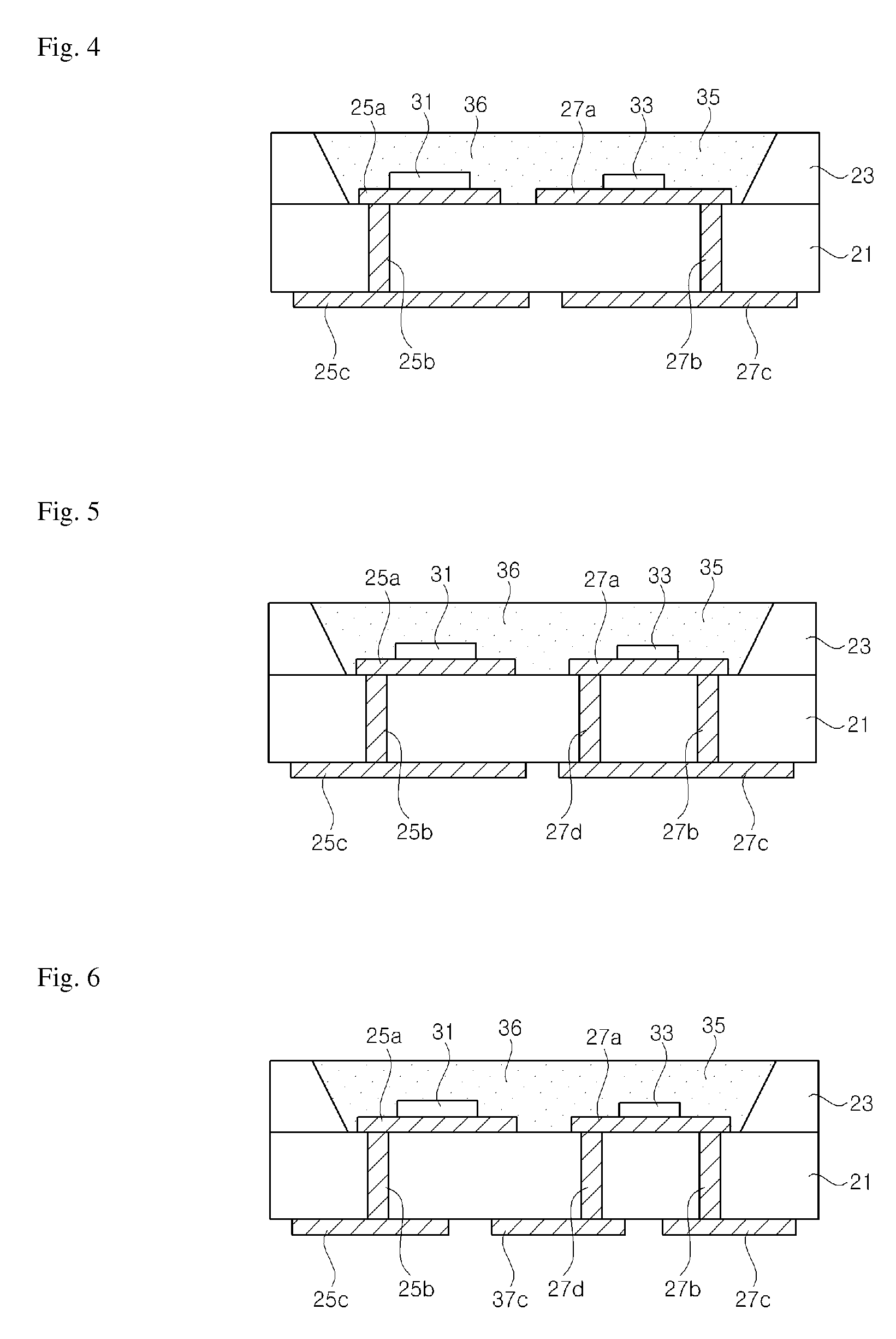
[0045]Referring to FIG. 1, the light emitting diode assembly according to this embodiment includes a base substrate 21, a housing 23, a first landing pad 25a, a second landing pad 27a, a first via 25b, a second via 27b, a first external pad 25c, ...


PUM


Abstract

Disclosed is a light emitting diode assembly. The light emitting diode assembly comprised: a red light emitting diode chip; a short-wavelength light emitting diode chip emitting a light having a wavelength relatively shorter than that of a light emitted from the red light emitting diode chip; a first heat-dispersion member for dispersing most of the heat generated in the short wavelength light emitting diode chip; and a second heat-dispersion member for dispersing most of the heat generated in the red light emitting diode chip. Further, the second heat-dispersion member has heat dispersion performance relatively superior to that of the first heat dispersion member. Thus, spectrum movement in the red light emitted from the red light emitting diode chip may be prevented so as to prevent a color-coordinate transformation during the operation time of same.

Description

CROSS-REFERENCE TO RELATED APPLICATIONS[0001]This application is the National Stage Entry of International Application PCT / KR2012 / 004180, filed on May 25, 2012 and claims priority from and the benefit of Korean Patent Application No. 10-2011-0052970, filed on Jun. 1, 2011, all of which are incorporated herein by reference in their entireties for all purposes as if fully set forth herein.BACKGROUND[0002]1. Filed[0003]The present invention relates to a light emitting diode assembly, and more particularly, to a light emitting diode assembly including a red light emitting diode chip.[0004]2. Discussion of the Background[0005]Light emitting diodes are used as light sources in various products. Particularly, light emitting diodes are used as light sources for backlight units, displays, lighting fixtures, and the like, and can emit white light through combination of light emitting diodes emitting various colors, or combination with phosphors. Particularly, white light can be realized throu...

Claims


Application Information

Patent Timeline
Patent Type & Authority Patents(United States)
IPC IPC(8): H01L33/64H01L27/15H01L25/075F21K99/00
CPCH01L33/64F21K9/13H01L25/0753H01L27/15H01L33/642H01L33/647H01L2224/48247H01L2224/48091H01L2924/00014H01L2924/00F21K9/23H01L33/50H01L33/62
Inventor LEE, CHUNG HOONKAL, DAE SUNGSEO, WON CHEOLYANG, YOUNG EUN
Owner SEOUL SEMICONDUCTOR
Why Eureka
Try Eureka