Engine cooling fan having dynamic unbalance compensation

a cooling fan and dynamic technology, applied in the field of engine cooling fans, can solve the problems of static unbalance, static unbalance, static unbalance, etc., and achieve the effect of preventing the disadvantage of the engine, preventing the unbalance from occurring, and facilitating the balancing process

Inactive Publication Date: 2011-09-29
ROBERT BOSCH GMBH
View PDF4 Cites 23 Cited by
  • Summary
  • Abstract
  • Description
  • Claims
  • Application Information

AI Technical Summary

Benefits of technology

[0007]Such an engine fan device has the advantage of affording a simple and automatable facility for balancing out the dynamic unbalance and preventing the disadvantages occurring due to the unbalance. According to the invention one, two or more balancing elements, for example, are fixed or wedged and/or bonded in one or more mounting contours in order to compensate for a dynamic unbalance. The balancing elements here are dimensioned or have a predefined weight and are positioned in the mounting contours so that a dynami...

Problems solved by technology

Inertial forces or static and dynamic unbalances are generally caused by uneven mass distributions of the rotating assemblies, such as the rotor or the armature of a motor and by the fan, for example, and by geometric and positional tolerances relative to the axis of rotation and the principal axis of inertia of the drive.
In the event of a parallel shift between the axis of rotation and the principal axis of inertia of a cooling fan with fan wheel mounted on the rotor shaft this leads to a static unbalance, for example.
If the axis of rotation is tilted relative to the principal axis of inertia, on the other hand, this produces a centrifugal moment, which is equi...

Method used


Image

  • Engine cooling fan having dynamic unbalance compensation
  • Engine cooling fan having dynamic unbalance compensation
  • Engine cooling fan having dynamic unbalance compensation

Examples


first embodiment

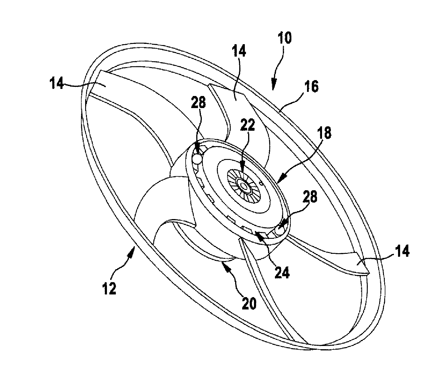
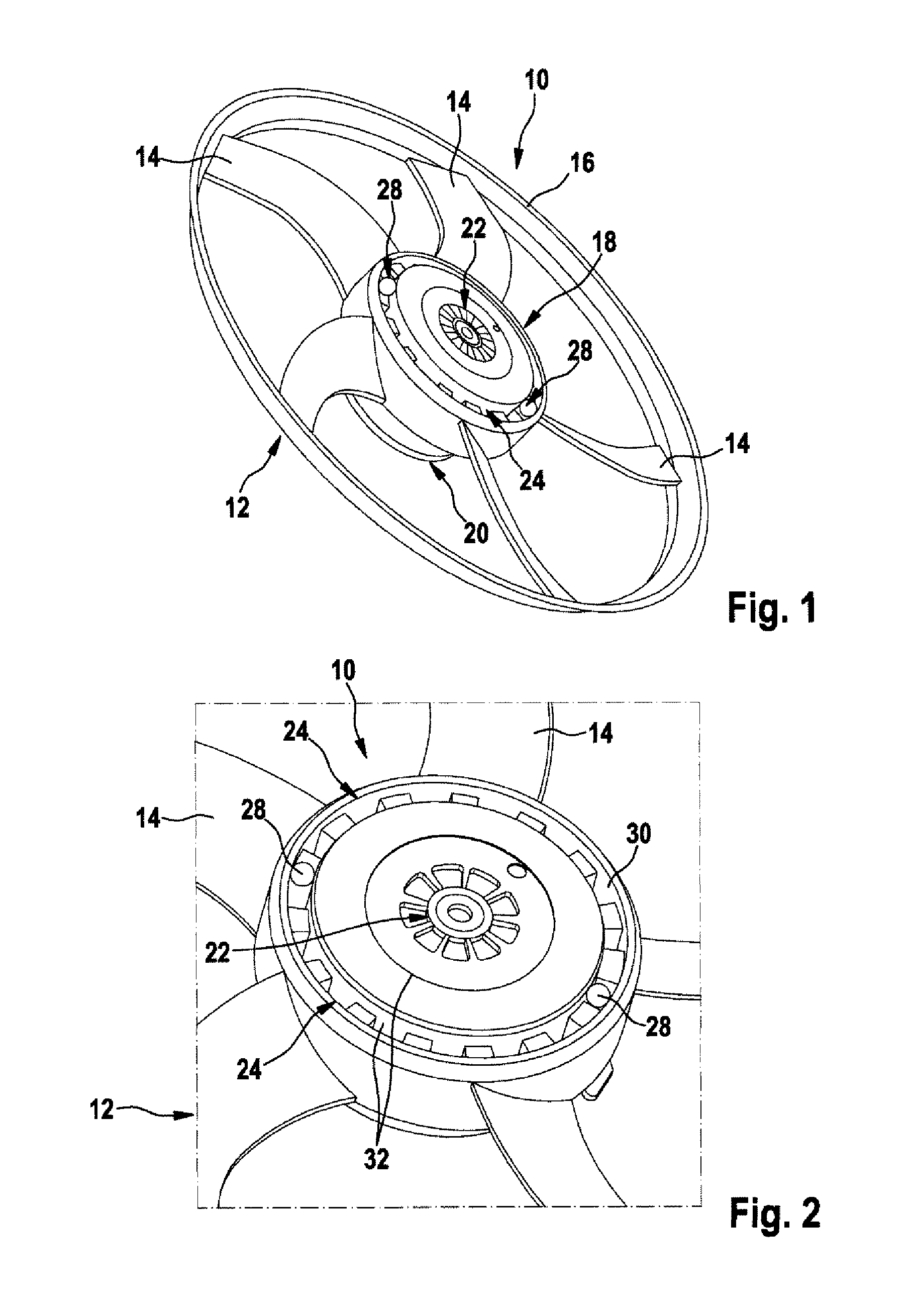
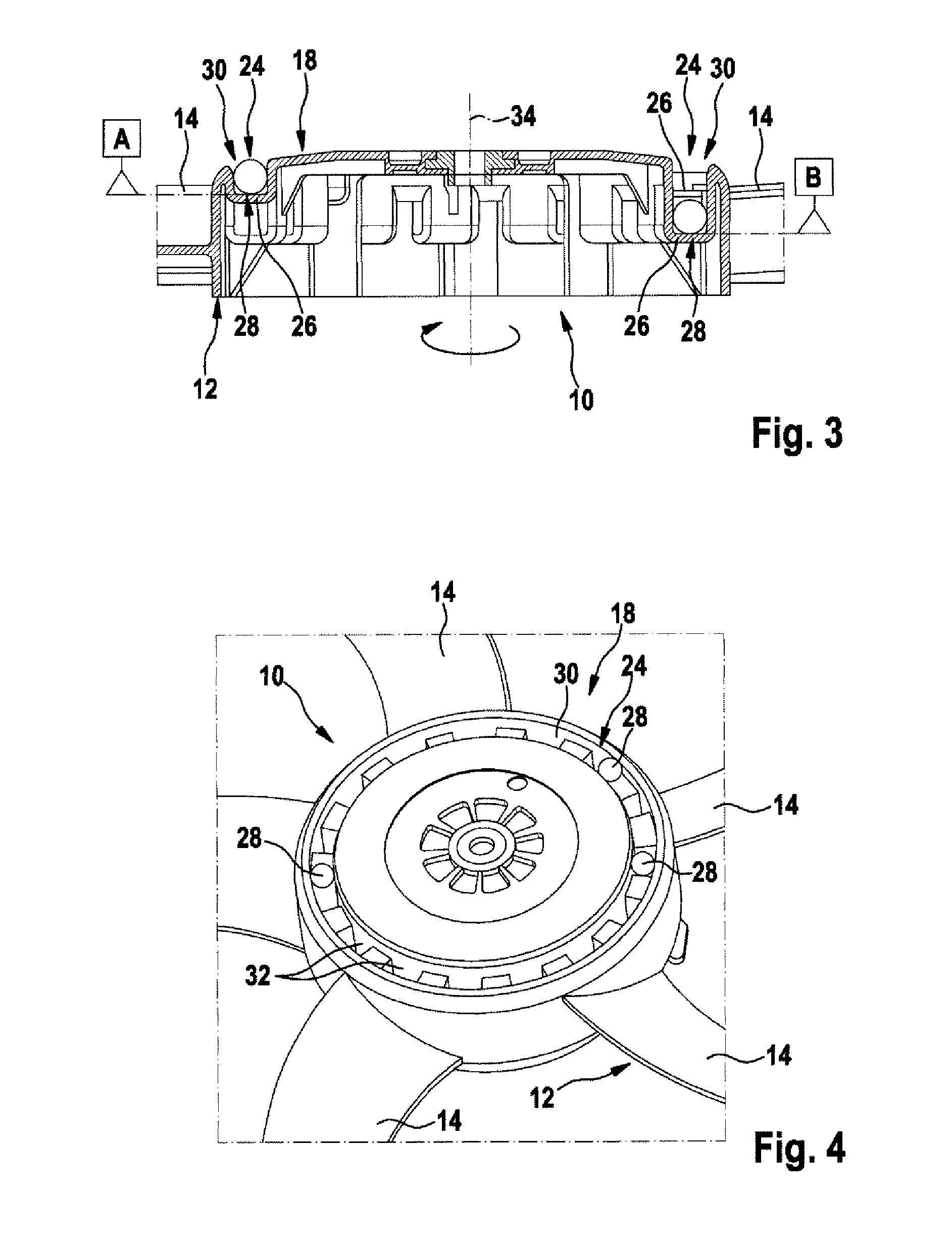
[0024]FIGS. 1, 2 and 3 show an engine fan device 10 according to the invention, in which a dynamic unbalance is compensated for. As is shown in FIG. 1, the engine fan device 10 here comprises a fan appliance 12, which comprises one or more blade elements 14, which on their outside are bounded by a fan wheel 16 and on their inside are molded onto a hub area 18 of the fan appliance 12, for example. The engine fan device 10 moreover comprises a motor 20 for driving the fan appliance 12. Here the fan appliance 12 may be coupled to the motor 20 by way of a drive carrier device 22, for example.

[0025]In order to compensate suitably for a dynamic unbalance of the engine fan device 10 and its fan appliance 12, the engine fan device 10 according to the first embodiment has a mounting contour 24, which has at least two, three or more planes 26, which are arranged on different levels. Here one, two, three or more balancing elements 28 can provided in the mounting contour 24. In this case the ba...

third embodiment

[0028]FIG. 5 shows a perspective view of an engine fan device 10 according to the invention. In this embodiment the mounting contour 24, here in the form of a groove 30, is formed around the circumference, one, two, three or more ribs 36 being provided, which interrupt the course of the groove 30 and the mounting contour 24. The ribs 36 may serve, for example, to divide a mounting contour 24 into multiple chambers 38, which are capable of accommodating one, two or more balancing elements 28, the chambers 38 here forming one, two or more planes 26. In the example in FIG. 5 the four chambers 38 each have both planes of rotation A and B, for example. The four chambers 38 may here have the same or a different number of depressions 32 for the mounting of balancing elements 28.

[0029]FIG. 6 also shows an engine fan device 10 according to a fourth embodiment of the invention. Here the engine fan device 10 or the fan appliance 12 likewise has a mounting contour 24 in the form of a groove 30,...

fifth embodiment

[0030]FIG. 7 shows a partial sectional view of an engine fan device 10 according to the invention. Here the engine fan device 10 or its fan appliance 12 has at least two mounting contours 24, which are arranged side by side running over part or all of the circumference, in this case in the hub area 18 of the engine fan device 10 or its fan appliance 12. The mounting contours 24 form two grooves 30, for example, which are arranged in the form of two concentric circles. Each of the mounting contours 24 or grooves 30 here has at least one or more planes 26 or planes of rotation 26. The first, inner groove 30 forms the plane of rotation A, for example, and the second, outer groove 30 forms the plane of rotation B. In principle, however, any of the mounting contours 24 may also alternate between at least two, three and more planes 26, as in the preceding embodiments. At the same time one, two, three or more balancing elements 28 may be provided in one or both mounting contours 24.

[0031]F...


PUM


Abstract

The invention relates to an engine fan device for a vehicle, characterized in that the engine fan device (10) has at least one or more receiving contours (24, 30, 50), in which one or more balancing elements (28) can be received, wherein at least one receiving contour (24) has at least two planes (26), and/or wherein at least two receiving contours (24) each have at least one plane (26), wherein both planes (26) are different from each other.

Description

BACKGROUND OF THE INVENTION[0001]The invention relates to an engine cooling fan of a motor vehicle, which is provided with a dynamic unbalance compensation device.[0002]Inertial forces or static and dynamic unbalances are generally caused by uneven mass distributions of the rotating assemblies, such as the rotor or the armature of a motor and by the fan, for example, and by geometric and positional tolerances relative to the axis of rotation and the principal axis of inertia of the drive. The geometric and positional tolerances here mean that the axis of rotation and the principal axis of inertia do not coincide. In the event of a parallel shift between the axis of rotation and the principal axis of inertia of a cooling fan with fan wheel mounted on the rotor shaft this leads to a static unbalance, for example. If the axis of rotation is tilted relative to the principal axis of inertia, on the other hand, this produces a centrifugal moment, which is equivalent in its effects to a mo...

Claims


Application Information

Patent Timeline
IPC IPC(8): F01D25/04
CPCF04D29/662F01P5/02
Inventor SCHNEIDER, TOBIASLIEDEL, MARKUSHELMING, THOMASSCHIED, HEIDRUN
Owner ROBERT BOSCH GMBH
Why Eureka
Try Eureka