Disk package for a centrifuge rotor

Inactive Publication Date: 2011-09-29
ALFA LAVAL CORP AB
View PDF9 Cites 24 Cited by
  • Summary
  • Abstract
  • Description
  • Claims
  • Application Information

AI Technical Summary

Benefits of technology

[0005]The object of the present invention is to provide a disk package which can b

Problems solved by technology

These areas are also difficult to reach during cleaning of the disk package, which means that in many applications it can be difficult to reach the hygienic requirements called for.
A

Method used


Image

  • Disk package for a centrifuge rotor
  • Disk package for a centrifuge rotor
  • Disk package for a centrifuge rotor

Examples


first embodiment

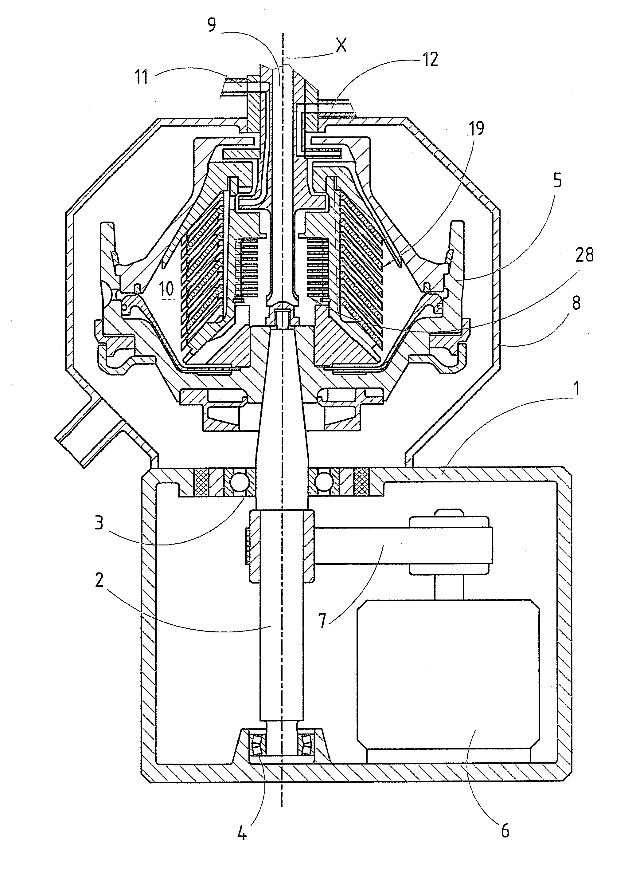
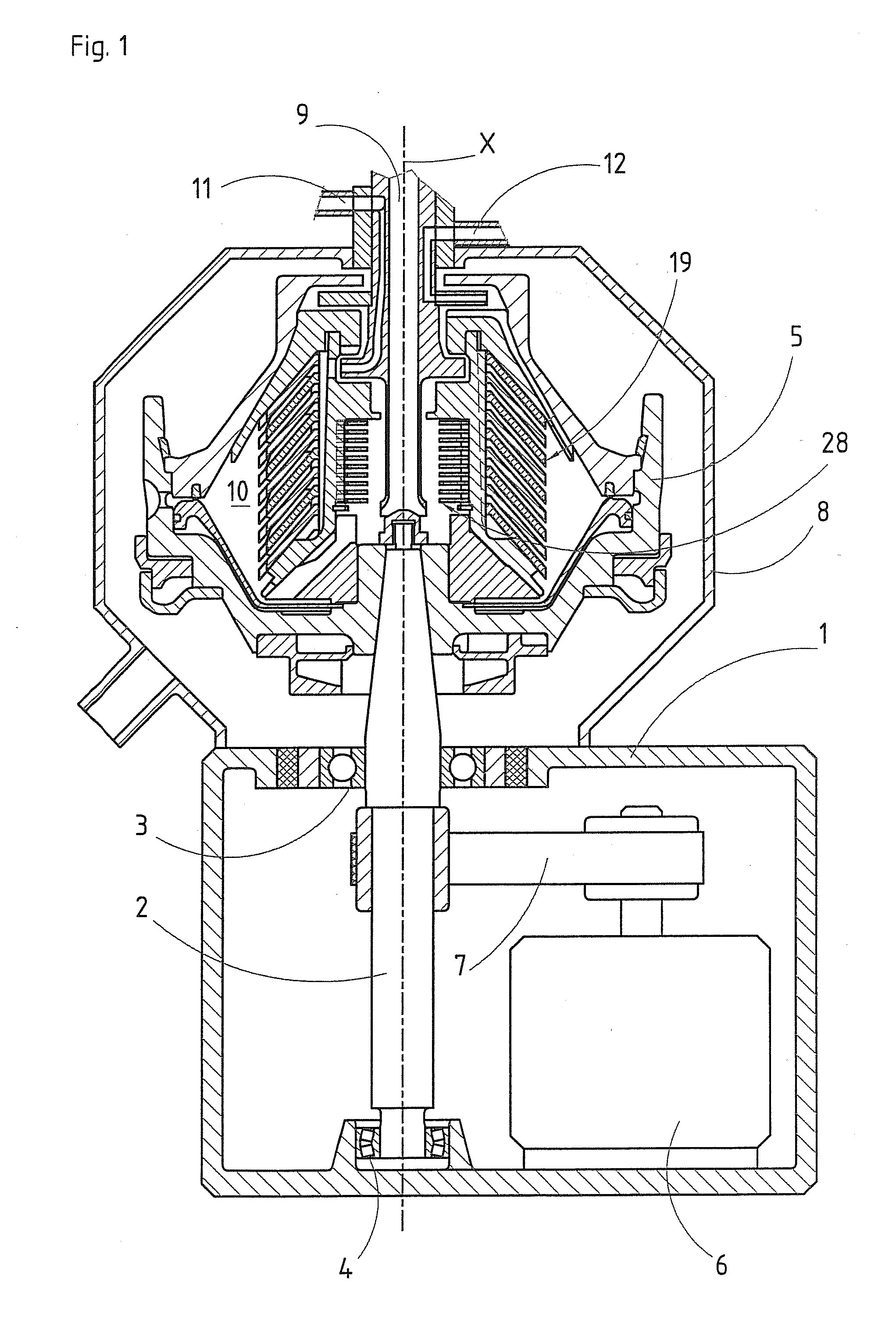
[0037]In the separation space 10, there is a disk package 19 which rotates with the centrifuge rotor 5. The disk package 19 comprises or is assembled of a plurality of separating disks 20 which are stacked onto each other in the disk package 19, see FIG. 2. A separating disk 20 is disclosed more closely in FIGS. 3 and 4. Each separating disk 20 extends around the axis x of rotation and rotates around the axis x of rotation in a direction R of rotation. Each separating disk 20 extends along a rotary symmetric, or virtually rotary symmetric, surface which tapers along the axis x of rotation, and has a tapering shape along the axis x of rotation with an outer surface 21, which is convex, and an inner surface 22, which is concave. The tapering shape of the separating disks 20 may also be conical or substantially conical, but it is also possible to let the tapering shape of the separating disks 20 have a generatrix which is curved inwardly or outwardly. The separating disks 20 thus have...

second embodiment

[0052]According to the disk package 19, see FIG. 6, also each second separating disk 20″ may comprise a number of distance members in the form of pressed first and second protrusions 31 and 32, i.e. all separating disks 20 are provided with first and second protrusions 31 and 32. In this case, the separating disks 20 mat be polar-positioned in such a way that a first protrusions 31 of the first separating disks 20′ are displaced in relation to the first protrusions 31 of the second separating disks 20″ in the disk package 19 seen in the direction of the axis x of rotation.

[0053]It is to be noted here that for achieving the above mentioned pre-tensioning in the disk package 19, it is possible to provide the disk package 19 with distance members 25 which can not be deformed and for instance be formed by conventional distance members which are brazed or welded to the separating disks 20, but which are located in a corresponding manner as the first and second protrusions 31 and 32. Such...

third embodiment

[0054]FIG. 7 discloses a third embodiment where the distance members 25 have a spot-like extension. Also in this embodiment, the height of the distance members 25 may vary with the distance of the spot-like distance members 25 from the axis x of rotation. These distance members 25 may advantageously also be configured as first protrusions 31 extending away from the outer surface 21 and second protrusions 32 extending away from the inner surface 22. Each protrusion 31, 32 may advantageously have a continuously convex shape seen in a section transversally to a peripheral direction and transversally to a radial direction. In this embodiment, the contact zone 33 may be defined to form a point abutment, or substantially a point abutment, against the inner surface 22 or the outer surface 21 of the adjacent separating disk 20. The protrusions 31 and 32 are displaced in relation to each other and may be provided at a distance from or adjacent to each other. Moreover, it is to mentioned here...


PUM

PropertyMeasurementUnit
Shapeaaaaaaaaaa
Widthaaaaaaaaaa
Areaaaaaaaaaaa

Abstract

The invention refers to a disk package for a centrifuge. The disk package comprises a plurality of separating disks provided on each other in the disk package. Each separating disk extends around an axis of rotation for the centrifuge rotor and has tapering shape with an inner surface and an outer surface along the axis of rotation. Each separating disk has inner edge, defining a central opening of the separating disk, and outer edge. Each separating disk is manufactured of a material. The separating disks comprise a plurality of first separating disks comprising a number of distance members, which extend away from the inner surface and/or outer surface. Each distance member comprises at least one contact zone abutting an outer surface and inner surface, respectively, of an adjacent separating disk in the disk package. The contact zone has a continuously convex shape seen in a cross section.

Description

FIELD OF THE INVENTION[0001]The present invention refers to a disk package of a centrifuge rotor of a centrifugal separator adapted for separation of components in a supplied medium, wherein the disk package comprises a plurality of separating disks provided on each.[0002]Today separating disks for disk packages in centrifuge rotors are normally manufactured through pressure turning of plane disks to a desired tapering shape, for instance a conical shape. The distance members, which define the distance between the separating disks in the disk package, are normally formed by loose flat elements which are attached to the outer surface of the separating disks through spot welding. One property of such distance members is that they have a relatively large contact area against the inner surface of the adjacent separating disk in the disk package. Another property is that gaps or thin interspaces are formed between the distance members and the outer surface of the separating disk at which...

Claims


Application Information

Patent Timeline
IPC IPC(8): B04B7/14
CPCB04B7/14B04B1/08B04B1/04B04B5/12B21D22/00
Inventor RUDMAN, LARS JOHANOLSSON, SVEN OLOV
Owner ALFA LAVAL CORP AB
Why Eureka
Try Eureka