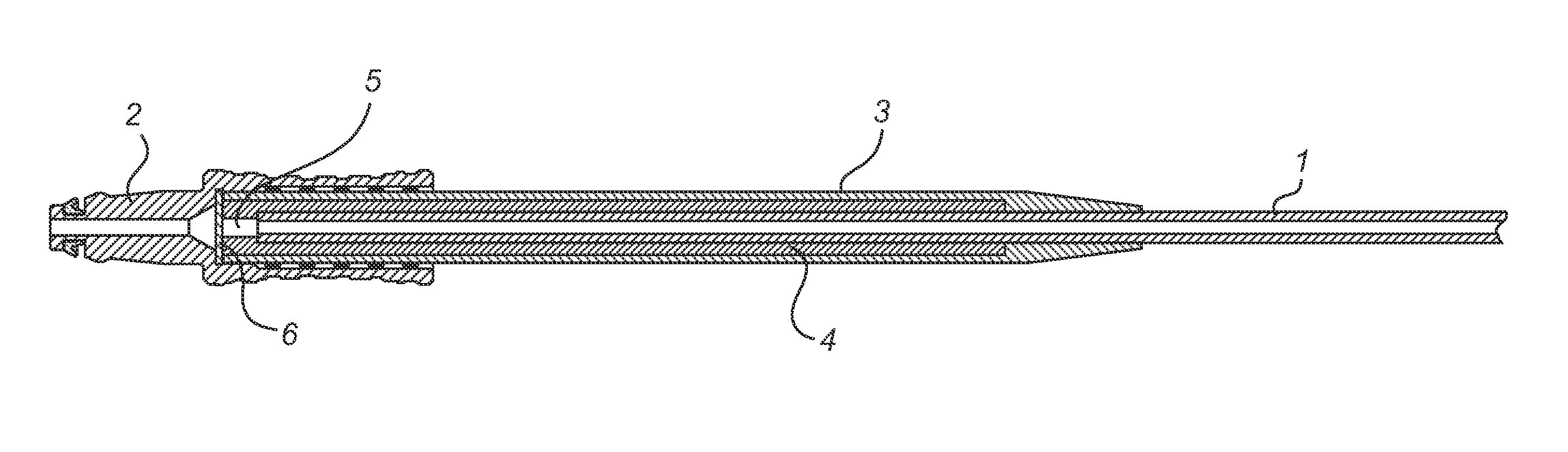
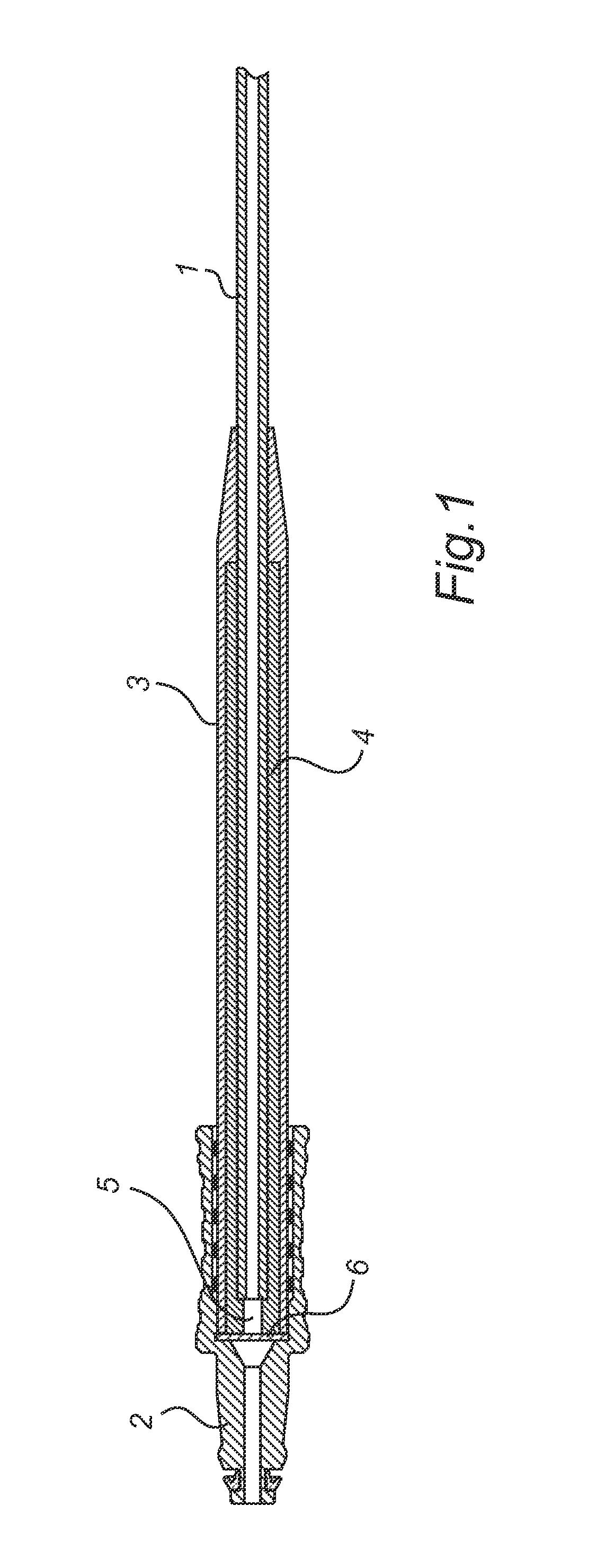
Gas sampling line

a gas sampling line and gas sampling technology, applied in the field of gas sampling lines, can solve the problems of distorting the gas sample flow, inaccurate readings at the sensor, adversely affecting the delicateness of the gas monitor, etc., and achieves the effects of high breath rate, low distortion, and high accuracy of gas components

Active Publication Date: 2011-09-29
JPMORGAN CHASE BANK NA
View PDF7 Cites 186 Cited by
  • Summary
  • Abstract
  • Description
  • Claims
  • Application Information

AI Technical Summary

Benefits of technology

The technical effect of this patent is that it provides a way to collect respiratory gases from patients without getting them wet or affecting the results with other substances like humidity. It also ensures accurate readings on important gases like carbon dioxide (CO2), nitrous oxide (N2O), and anesthetics. This allows for better monitoring of patient health during procedures where these gases are being used.

Problems solved by technology

The technical problem addressed in this patent text relates to improving the accuracy and reliability of respiratory gas monitors by preventing distortion of the gas samples due to water vapor and other contaminants while still effectively removing them. Existing methods have included adding water traps or separators but they must achieve high levels of efficiency and capacity without compromising the gas sample flow. There is thus a need for improved designs that address these issues.

Method used


Image

  • Gas sampling line
  • Gas sampling line

Examples


examples

[0047]Characteristics and advantages of the present invention are further illustrated by the following, non-limiting, examples.

Preparation of Gas Sampling Tubes According to the Invention

[0048]Gas sampling tubes according to the invention were prepared by extrusion of a polyether block amide material (available from Atofina under the trade name Pebax®) to form a tubing having an inner diameter of 1 mm and an outer diameter of 2.5 mm, and subsequent cutting of the tubing to obtain gas sampling tubes having a length of 2 m. The composition of the polyether block amide material is shown in Table 1.

TABLE 1Gas samping tube according to the present inventionTube no.Composition1polyether block amide material of55% polyethyleneoxide and45% polyamide-12

Preparation of Comparative Gas Sampling Tubes

[0049]As comparative gas sampling tubes were used 2 m lengths of four different tubings having an inner diameter of 1 mm and an outer diameter of 2.5 mm. The composition of the tubing materials and ...


PUM


Abstract

A gas sampling line having a channel for conducting respiratory gases from a patient respiratory interface to a gas monitor, the gas sampling line comprising, i.a., a gas sampling tube comprised of a polyether block amide material, the polyether segments of which comprise polyethyleneoxide. Use of a tube comprised of a polyether block amide material, the polyether segments of which comprise polyethyleneoxide, for sampling of respiratory gases; and a method for sampling of respiratory gases, the method comprising conducting respiratory gases through such a tube. A gas analysis system for analysing respiratory gases, comprising a gas sampling line as defined above and a gas monitor connectable to the gas sampling line.

Description


Claims


Application Information

Patent Timeline
Owner JPMORGAN CHASE BANK NA
Why Eureka
Try Eureka