Sole Structure for a Shoe

a technology for shoe soles and bending resistances, applied in the field of shoe sole structure, can solve the problems of small bending resistance and energy loss of shoes, and achieve the effects of reducing energy loss during running, increasing the amount of restraint easily, and smooth ride feeling during running

Inactive Publication Date: 2011-10-06
MIZUNO CORPORATION
View PDF0 Cites 26 Cited by
  • Summary
  • Abstract
  • Description
  • Claims
  • Application Information

AI Technical Summary

Benefits of technology

[0088]According to the second aspect of the present invention, as with the first aspect of the present invention, due to the function of the bending restriction member, not only an energy loss during running can be decreased and a smooth ride feeling during running can be achieved but also a downward force imparted from a shoe wearer's foot at the time of sole contact with the ground can be supported by the plate. Moreover, since the plate is disposed above the bottom portion of the groove, the bottom portion of the groove can be prevented from being deformed by the downward force imparted from the shoe wearer's foot and a neutral axis dur

Problems solved by technology

As a result, the push off motion of the sole forefoot region cannot be conducted in a smooth (i.e. rapid, secure and efficient) manner.
However, since the sole structure is so constructed as to make the sole rear foot region bend relative to the sole forefoot region, the bending

Method used


Image

  • Sole Structure for a Shoe
  • Sole Structure for a Shoe
  • Sole Structure for a Shoe

Examples


first embodiment

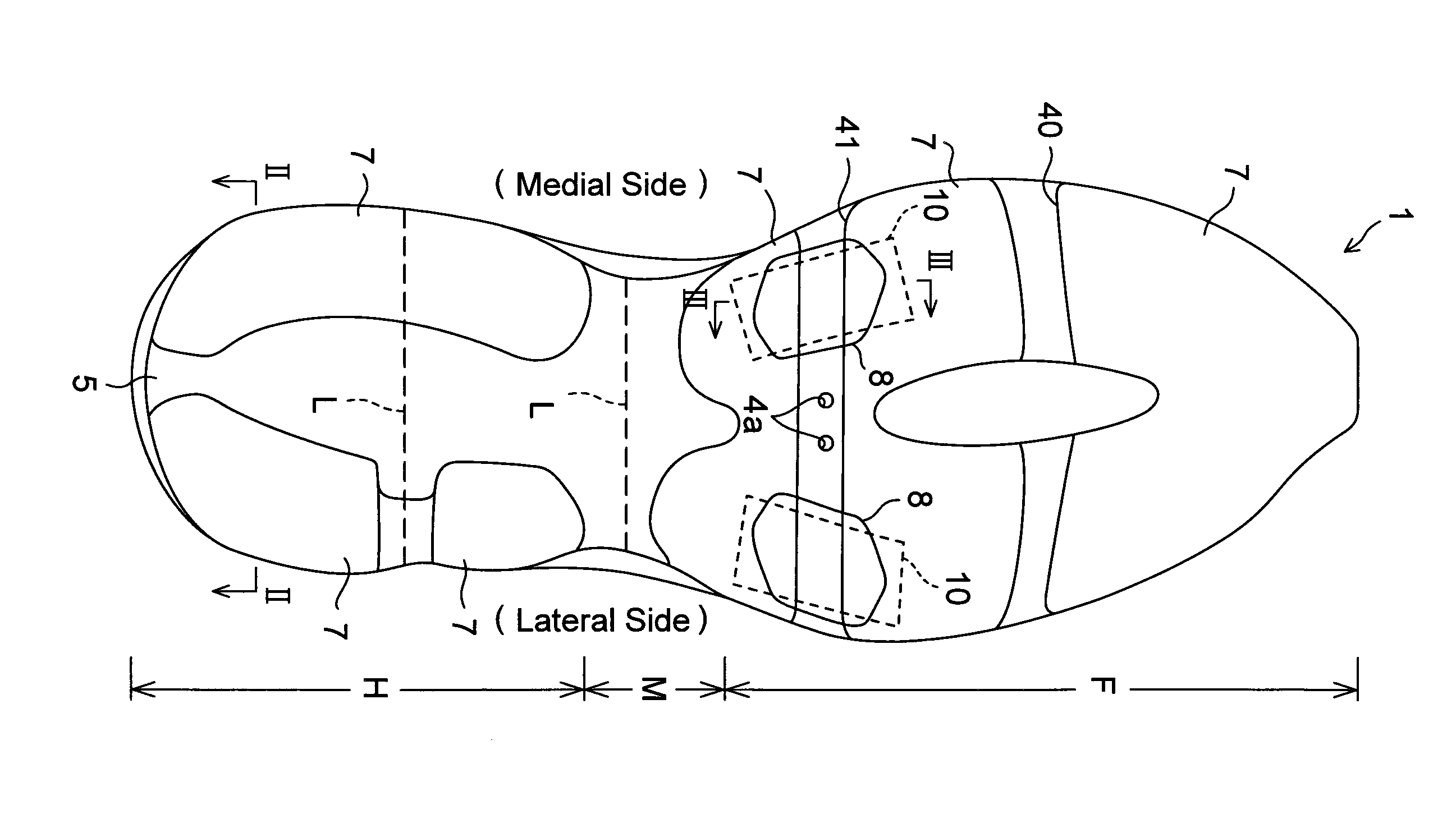
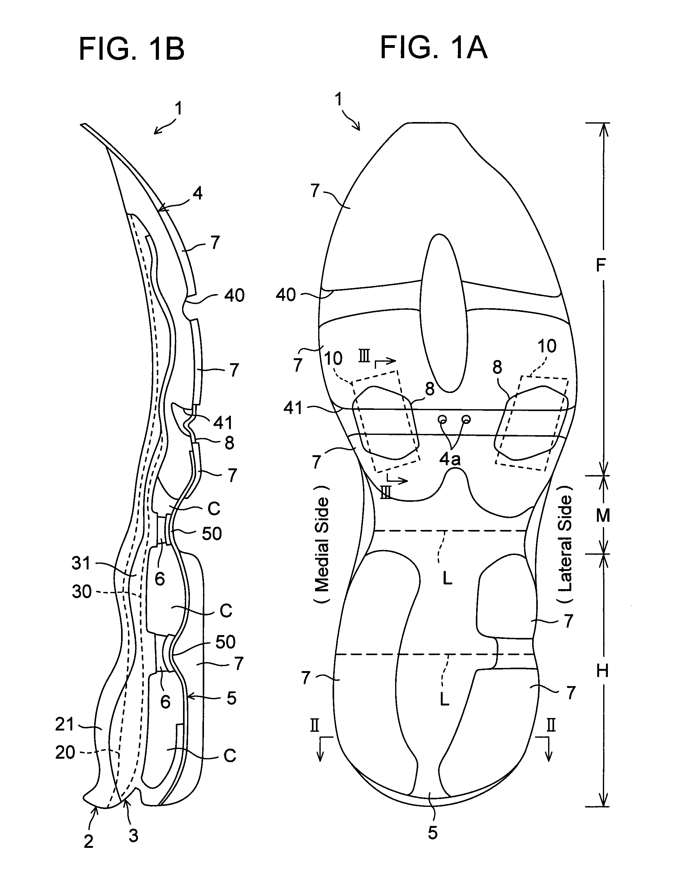
[0110]Referring now to the drawings, FIGS. 1A to 7C show a sole structure or a sole assembly for a shoe according to a first embodiment of the present invention. In these drawings, like reference numbers indicate identical or functionally similar elements.

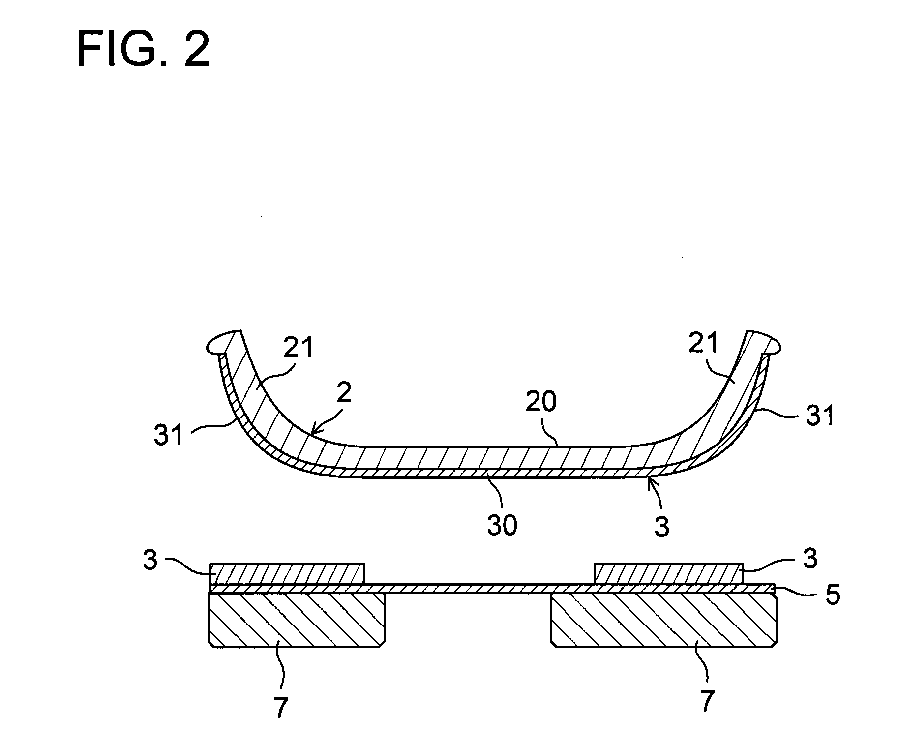
[0111]As shown in FIGS. 1A and 1B, a sole structure 1 for a shoe comprises an upper midsole 2 formed of a soft elastic material and extending longitudinally from a heel region H through a midfoot region M to a forefoot region F of the shoe, an upper plate 3 formed of a hard elastic material, fixedly attached to the bottom of the upper midsole 2 and extending longitudinally from the heel region H through the midfoot region M to the forefoot region F of the shoe, a lower midsole 4 formed of a soft elastic material, fixedly attached to the bottom of the upper plate 3 and disposed mainly at the forefoot region F of the shoe, and a lower plate 5 of hard elasticity which extends longitudinally mainly from the heel region H to the midfoot...

second embodiment

[0169]In the first embodiment, the groove 41 formed on the lower midsole 4 has an inverted V-shape in cross section but the present invention is not limited to such an example. The cross sectional shape of the groove 41 may be inverted U-shaped or circular shaped. Any suitable shape can be adopted as long as the groove 41 opens to the ground contact side. In all cases, the sole bends around the bottom of the groove of an inverted V-shape, inverted U-shape, circular shape or any other shape as the bending or flex point during bending of the sole.

[0170]In any of the cases where the groove 41 has a different shape in cross section, the bending restriction member 10 disposed in the groove 41 has the upwardly protruding bent portion 10a, which is not fixedly attached to the bottom of the groove 41. Preferably, the bending restriction member 10 is not fixed to the sidewall of the groove 41 either and located away from the sidewall of the groove 41.

third embodiment

[0171]In the first embodiment, the bending restriction member 10 has an inverted V-shape in longitudinal section but the present invention is not limited to such an example. The longitudinal sectional shape of the bending restriction member 10 may be inverted U-shaped or circular shaped. Any suitable shape can be adopted in accordance with the cross sectional shape of the groove 41.

[0172]Also, as shown in FIG. 8, the bending restriction member may have a downwardly protruding bent portion 10′a in a V-shape or U-shape. In this case, an elastic cover member 8′ that covers the downwardly protruding bent portion 10′a of the bending restriction member 10′ from below also has a downwardly protruding bent shape along the bent shape of the bending restriction member 10′. In FIG. 8, reference numbers similar to those of the first embodiment indicate identical or functionally similar elements.

[0173]In this case, in the beginning stage of bending of the sole, the bending restriction member 10′...


PUM


Abstract

The sole structure 1 has an upper plate, a lower midsole located under and fixedly attached to the upper plate, and having a laterally extending groove opening to the bottom side of the lower midsole, and a bending restriction member formed in a bent shape and spanning the groove longitudinally between the front edge and the rear edge of the opening of the groove. During the beginning phase of sole bending, the bending restriction member allows for the sole to bend till the bending restriction member gradually extends toward a straight shape from the bent shape and becomes taut between the front edge and the rear edge of the opening of the groove. During the advanced phase of the sole bending, when the bending restriction member experiences a force from the taut state, it functions so as to restrict the sole from bending.

Description

BACKGROUND OF THE INVENTION[0001]The present invention relates generally to a sole structure for a shoe, and more particularly, to an improved sole structure for decreasing an energy loss during running.[0002]Mizuno proposed a sole structure such as shown in WO 2006 / 070549 for improving bendability of a sole forefoot region of a shoe. The sole structure is comprised of a longitudinally extending upper plate disposed on an upper side of the sole forefoot region and a longitudinally extending lower plate disposed under and located away from the upper plate and having an undulated shape such that a longitudinal path length of the lower plate is greater than a longitudinal path length of the upper plate.[0003]In this case, during bending deformation of the sole forefoot region, the lower plate can further extend due to the undulated shape of a greater longitudinal path length and as a result the lower plate does not hinder bending deformation of the sole forefoot region, thus improving ...

Claims


Application Information

Patent Timeline
IPC IPC(8): A43B13/12A43B13/14
CPCA43B13/141A43B13/12
Inventor IUCHI, KAZUNORISATO, NATSUKITAKESHITA, TAKESHI
Owner MIZUNO CORPORATION
Why Eureka
Try Eureka