Evaporator having cold thermal energy storage function

Active Publication Date: 2011-10-06
MAHLE INT GMBH
View PDF13 Cites 63 Cited by
  • Summary
  • Abstract
  • Description
  • Claims
  • Application Information

AI Technical Summary

Benefits of technology

According to the evaporator with a cool storage function of par. 1), cool storage material containers filled with a cool storage material are disposed in some of all the air-passing clearances, and fins are disposed in the remaining air-passing clearances. Therefore, even when the effective core area is made equal to that of the evaporator with a cool storage function described in Patent Document 1, the number of the refrigerant flow tube sections does not decreases. Accordingly, a drop in cooling performance can be suppressed. Furthermore, since the cool storage material containers are joined to the refrigerant flow tube sections, a low temperature refrigerant flowing through the refrigerant flow tube sections enables storage of cool in the cool storage material within the cool storage material containers. Therefore, cool can be efficiently stored in the cool storage material.
According to the evaporator with a cool storage function of par. 2), each cool storage material container includes a plurality of convex portions projecting outward from opposite side surfaces thereof, and projecting ends of the convex portions are joined to the corresponding refrigerant flow tube sections. Therefore, even at the air-passing clearances in which the cool storage material containers are disposed, the convex portions form gaps between the refrigerant flow tube sections and the cool storage material containers, so that air flows through the gaps. Accordingly, an increase in air-passage resistance can be suppressed. Furthermore, condensed water produced on the outer surfaces of the refrigerant flow tube sections can be drained through the gaps formed between the refrigerant flow tube sections and the cool

Problems solved by technology

Incidentally, an ordinary car air conditioner has a problem in that, when an engine of an automobile in which the air conditioner is mounted is stopped, a compressor driven by the engine is stopped, and supply of refrigerant to an evaporator stops, whereby the cooling capacity of the air conditioner sharply drops.
However, t

Method used


Image

  • Evaporator having cold thermal energy storage function
  • Evaporator having cold thermal energy storage function
  • Evaporator having cold thermal energy storage function

Examples


Embodiment Construction

An embodiment of the present invention will next be described with reference to the drawings.

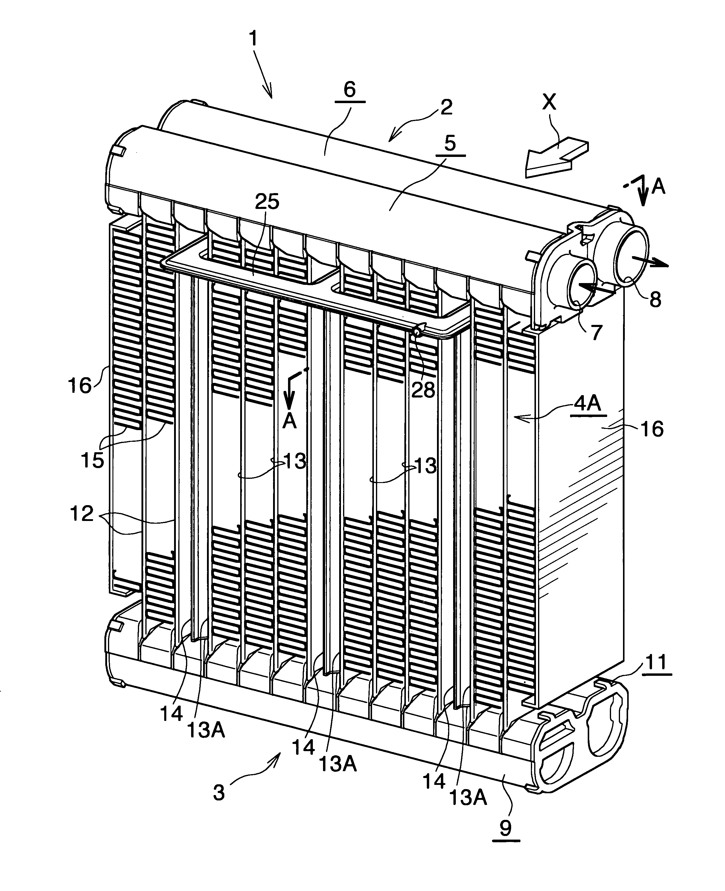
In the following description, the downstream side (a direction represented by arrow X in FIG. 1) with respect to an air flow direction will be referred to as the “front,” and the opposite side as the “rear.” Further, the upper, lower, left-hand, and right-hand sides as viewed rearward from the front side; i.e., the upper, lower, left-hand, and right-hand sides of FIG. 1, will be referred to as “upper,”“lower,”“left, and “right,” respectively.

In the following description, the term “aluminum” encompasses aluminum alloys in addition to pure aluminum.

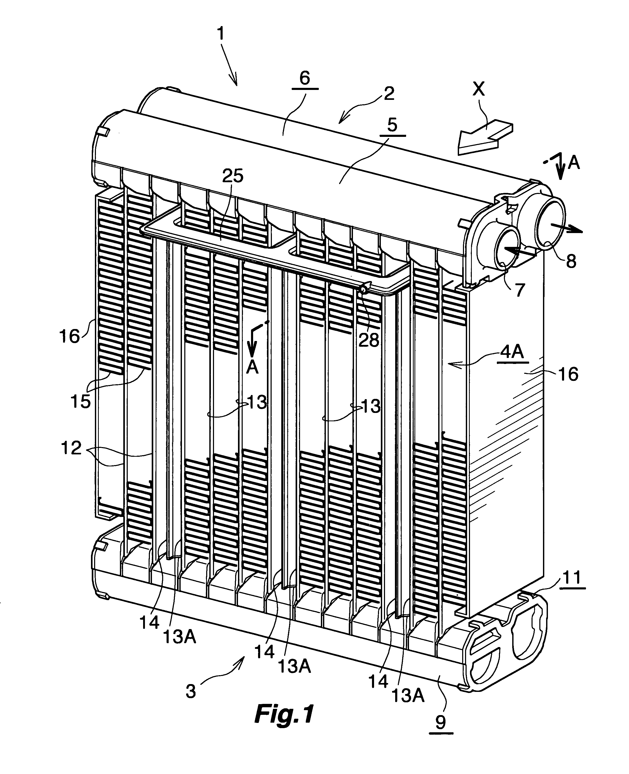
FIG. 1 shows the overall configuration of an evaporator with a cool storage function according to the present invention, and FIGS. 2 and 3 show the configurations of essential portions of the evaporator.

As shown in FIGS. 1 and 2, an evaporator with a cool storage function (1) includes a first header tank (2) and a second header tank (3) formed of al...


PUM


Abstract

An evaporator (1) with a cool storage function includes a plurality of flat refrigerant flow tubes (12) disposed in parallel such that their width direction coincides with an air flow direction and they are spaced from one another. Air-passing clearances (13, 13A) are formed between adjacent refrigerant flow tubes (12). Cool storage material containers (14) filled with a cool storage material are disposed in some (13A) of all the air-passing clearances (13, 13A), and each cool storage material container (14) is brazed to the refrigerant flow tubes (12) located on opposite sides thereof. Corrugated fins (15) are disposed in the remaining air-passing clearances (13), and each fin (15) is brazed to the refrigerant flow tubes (12) located on opposite sides thereof. Each cool storage material container (14) includes a plurality of convex portions (23) projecting outward from opposite side surfaces thereof, and projecting ends of the convex portions (23) are joined to the corresponding refrigerant flow tubes (12). This evaporator with a cool storage function can suppress a drop in cooling performance.

Description

TECHNICAL FIELDThe present invention relates to an evaporator with a cool (cold thermal energy) storage function for use in a car air conditioner for a vehicle in which an engine serving as a drive source for a compressor is temporarily stopped when the vehicle is stopped.BACKGROUND ARTIn recent years, in order to protect the environment and improve fuel consumption of automobiles, there has been proposed an automobile designed to automatically stop the engine when the automobile stops, for example, so as to wait for a traffic light to change.Incidentally, an ordinary car air conditioner has a problem in that, when an engine of an automobile in which the air conditioner is mounted is stopped, a compressor driven by the engine is stopped, and supply of refrigerant to an evaporator stops, whereby the cooling capacity of the air conditioner sharply drops.As one measure to solve such a problem, imparting a cool storage function to the evaporator has been considered, to thereby enable co...

Claims


Application Information

Patent Timeline
IPC IPC(8): F25B39/02
CPCB60H1/00335B60H1/005F28D1/0333F28D1/05366F28D20/02F25B39/028F28F17/005Y02E60/145F28D2020/0008F28D2021/0085F28D2020/0013F25B39/02F25B2339/0242Y02E60/14
Inventor TAKAGI, MOTOYUKI
Owner MAHLE INT GMBH
Why Eureka
Try Eureka