Pipeline protection systems

a protection system and pipeline technology, applied in the direction of fluid pressure control, water supply installation, functional valve types, etc., can solve the problems of overpressure in the pipeline, the pipeline is a major cost element of the fluid extraction system, and the cost-effective implementation of this for long pipelines

Inactive Publication Date: 2011-10-06
GE OIL & GAS UK LTD
View PDF6 Cites 40 Cited by
  • Summary
  • Abstract
  • Description
  • Claims
  • Application Information

AI Technical Summary

Benefits of technology

[0015]The present invention also comprises a pipeline protection system compr...

Problems solved by technology

Consequently, the pipeline is a major cost element of the fluid extraction system.
For a pipeline to withstand such pressure would require it to have a substantial wall thickness, and it is not cost-effective to implement this for long pipelines.
However, a failure of the pressure reducing device may result in overpressure in the pipeline with disastrous results.
Thus, loss of electrical or hydraul...

Method used


Image

  • Pipeline protection systems
  • Pipeline protection systems

Examples


Embodiment Construction

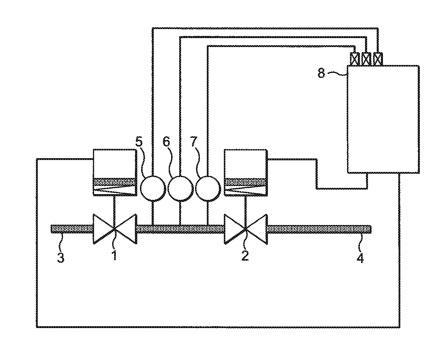
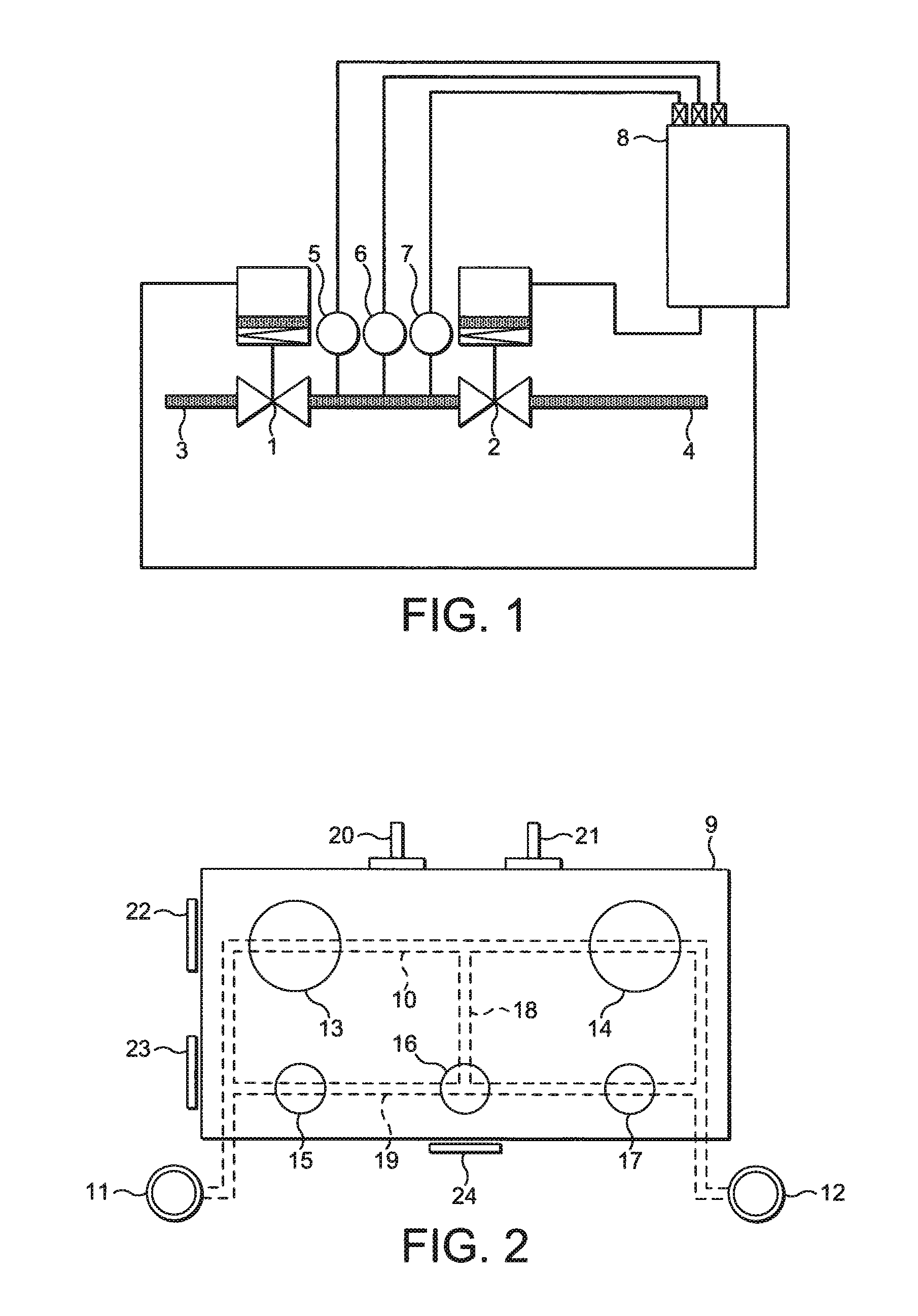
[0019]Referring to FIG. 2, reference numeral 9 denotes a metallic block in the form of a one-piece machined forging of, for example, chrome-molybdenum steel formed internally with a bore 10 which communicates with an input connector 11 and an output connector 12 so that the arrangement can be coupled in a hydrocarbon fluid pipeline of a subsea well. Reference numerals 13 and 14 denote two HIPPS barrier valves in series with each other and so that they are coupled in the pipeline via bore 10.

[0020]Inside the block 10 there also two bypass valves (not shown) and, in the particular example, three vent valves 15, 16 and 17, connected in the arrangement via machined bores 18 and 19 in the block 9. In operation, a vent line from the vent valves vents into a low pressure flow line.

[0021]Reference numerals 20 and 21 denote pressure sensors mounted on the block and connected, in use of the arrangement, to an SCM. Although only two are shown, in practice four are preferably used, the arrangem...


PUM


Abstract

A valve arrangement for a pipeline protection system comprises a plurality of barrier valves in series with each other for coupling in a pipeline, wherein the valves are received in a metallic block.

Description

CROSS-REFERENCE TO RELATED APPLICATIONS[0001]This is a national stage application under 35 U.S.C. §371(c) of prior-filed, co-pending PCT patent application serial number PCT / GB2009 / 051646, filed on Dec. 3, 2009, which claims priority to British patent application serial number 0822597.1, filed on Dec. 11, 2008, each of which is hereby incorporated by reference in its entirety.BACKGROUND OF THE INVENTION[0002]1. Field of the Invention[0003]This invention relates to pipeline protection systems for detecting and reducing overpressure in a fluid pipeline.[0004]2. Description of the Prior Art[0005]Hydrocarbon wells, for example subsea oil wells, require a pipeline through which the hydrocarbon fluid is transported. In the case of subsea wells, these may be of substantial length, sometimes several tens of kilometres long. Consequently, the pipeline is a major cost element of the fluid extraction system. Many subsea wells have to contend with very high fluid pressures, for example as high ...

Claims


Application Information

Patent Timeline
IPC IPC(8): F17D5/00
CPCF17D1/20F16K17/02Y10T137/87917F17D5/00F17D5/02
Inventor JONES, DAVID JOHNSIMS, RICHARD BARRY
Owner GE OIL & GAS UK LTD
Why Eureka
Try Eureka