
Low thermal strain multi-cooler

a heat exchanger and low thermal strain technology, applied in the field of multi-cooling heat exchangers, can solve the problems of high thermal strain of the cooling heat exchanger, increased labor and production time, and still required additional labor and production time, and achieve the effect of reducing the thermal strain

Inactive Publication Date: 2011-10-06
DENSO INTERNATIONAL AMERICA
View PDF13 Cites 19 Cited by
  • Summary
  • Abstract
  • Description
  • Claims
  • Application Information

AI Technical Summary

Benefits of technology

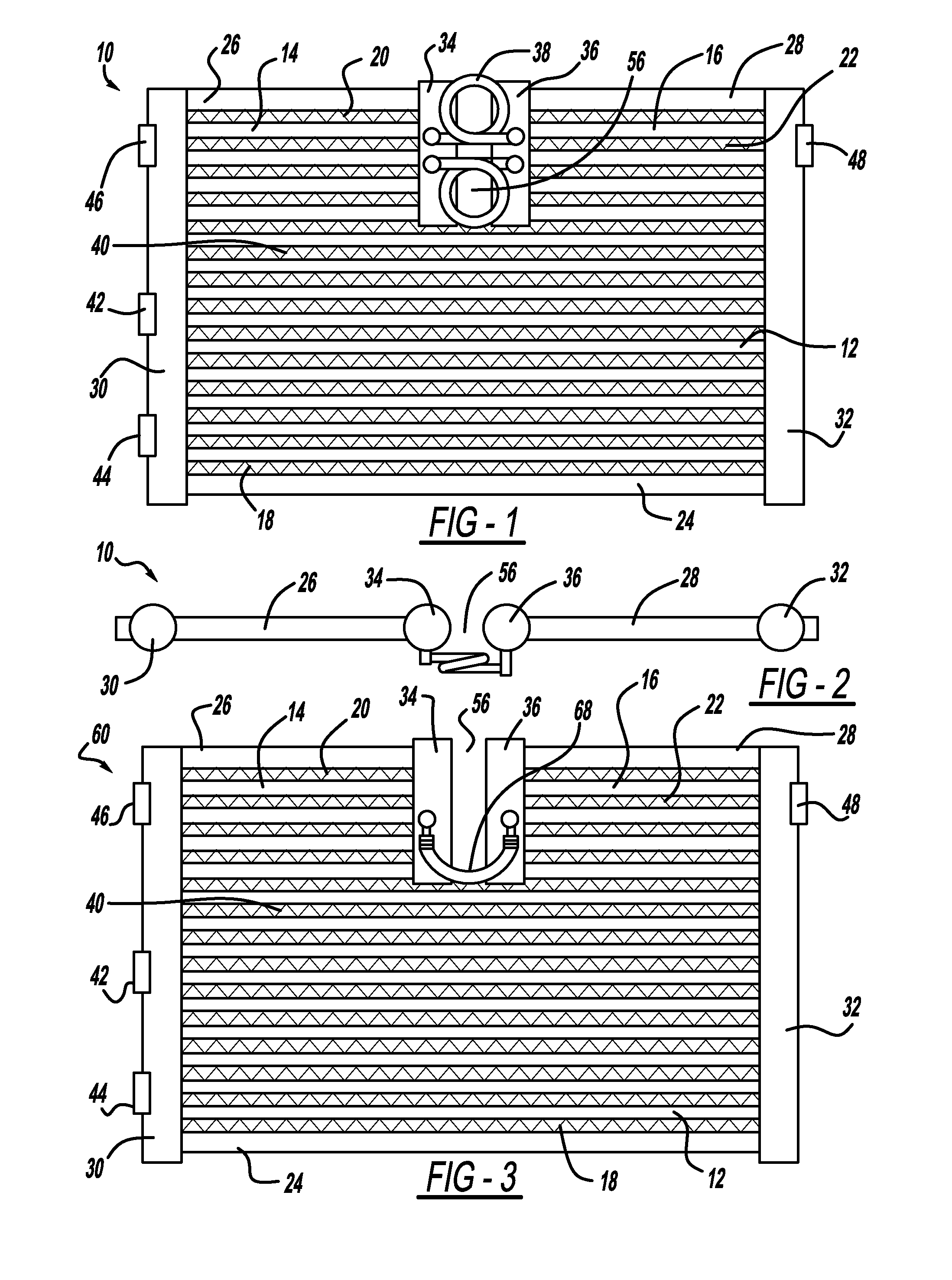
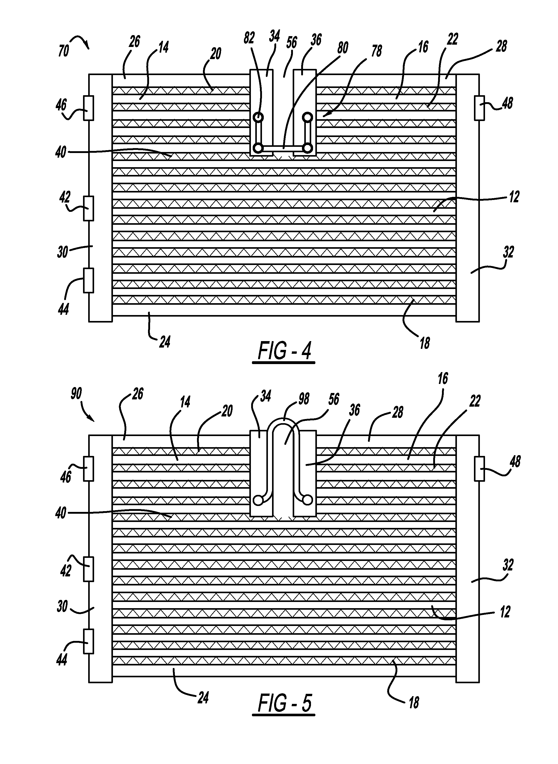
[0007]The present disclosure allows for the cooling of two or more fluids which flow in parallel through different sections of the plurality of tubes. The thermal strain is reduced in the present disclosure by providing intermediate tanks between the two header tanks. The two tanks are spaced from each other to define an open gap between them which allows for the difference in thermal expansion of the different sections of the heat exchanger.

Problems solved by technology

These multi-cooler heat exchangers develop a high amount of thermal strain.
This method is effective but it adds labor and production time to the process.
The saw cut in the insert or side plate reduces this thermal strain but it still requires additional labor and production time.

Method used


Image

  • Low thermal strain multi-cooler
  • Low thermal strain multi-cooler
  • Low thermal strain multi-cooler

Examples


Embodiment Construction

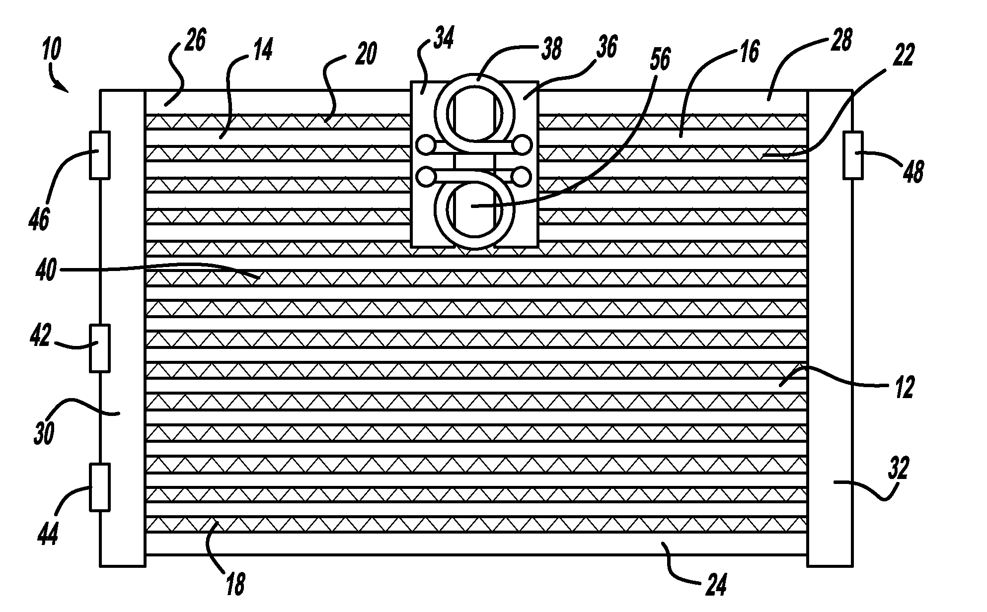
[0021]Example embodiments will now be described more fully with reference to the accompanying drawings. Referring now to FIGS. 1 and 2, a heat exchanger 10 in accordance with the present disclosure is illustrated. Heat exchanger 10 comprises a first plurality of tubes 12, a second plurality of tubes 14, a third plurality of tubes 16, a first plurality of fins 18, a second plurality of fins 20, a third plurality of fins 22, a first side plate 24, a second side plate 26, a third side plate 28, a first header tank 30, a second header tank 32, a first intermediate tank 34, a second intermediate tank 36 and one or more flexible jumper tubes 38.

[0022]Each of the first, second and third plurality of tubes 12, 14, 16 are arranged in parallel to each other and each tube is flat so that the direction of the air flow (perpendicular to the page in FIG. 1) coincides with the longer portion of the flat tube. The flat surfaces of the first, second and third plurality of tubes 12, 14, 16 are couple...


PUM


Abstract

A heat exchanger with multi-flow capabilities includes a pair of intermediate tanks located between a pair of header tanks. An open gap is provided between the two intermediate tanks. A first plurality of tubes extend between the header tanks. A second plurality of tubes extend between one of the header tanks and one of the intermediate tanks. A third plurality of tubes extend between the other header tank and the other intermediate tank. In a two flow system, the two intermediate tanks are in fluid communication through a flexible jumper tube. In a three flow system the two intermediate tanks are isolated from each other. The open gap between the intermediate tanks allows for the uneven heat expansion between the various fluid flows.

Description

FIELD[0001]The present disclosure relates to a heat exchanger. More particularly, the present disclosure relates to a multi-cooling heat exchanger for cooling two or more fluids while reducing the strain on the heat exchanger which occurs due to the different temperatures of the two or more fluids.BACKGROUND[0002]This section provides background information related to the present disclosure which is not necessarily prior art.[0003]The conventional multi-cooling heat exchanger includes a core portion having a plurality of tubes, a header tank attached to both ends of the tubes, a plurality of fins disposed between adjacent tubes and an insert or side plate that provides stability to the heat exchanger. The header tanks are separated along their length to provide two or more separate cooling sections for the heat exchanger. A first fluid flows through the first section of the header tanks and tubes and a second fluid flows through the second section of the header tanks and tubes. Typi...

Claims


Application Information

Patent Timeline
Patent Type & Authority Applications(United States)
IPC IPC(8): F28F9/02
CPCF28D1/0426F28D1/05391F28F2265/26F28F9/02F28D2001/028
Inventor PIGGOTT, ALFRED
Owner DENSO INTERNATIONAL AMERICA
Learn More