Optical angular sensor and optical rotational speed sensor

a technology of optical rotational speed and optical angular sensor, which is applied in the direction of instruments, devices using optical means, material analysis, etc., can solve the problems of limiting the usefulness of small portable devices, clicking and popping of users, and affecting the user's enjoyment of listening experience, etc., and achieves the effect of being readily recognized

Inactive Publication Date: 2011-10-06
NXP BV
View PDF7 Cites 22 Cited by
  • Summary
  • Abstract
  • Description
  • Claims
  • Application Information

AI Technical Summary

Problems solved by technology

During the turning of the knob, the user may encounter clicks and pops owing to a less than solid electrical connection of the rotating conductive contact and the surface of the variable resistor.
Such pops may diminish the user's enjoyment of the listening experience, at a minimum or such pops may be large transient voltages sent to the speakers that damage them.
Furthermore, the mechanical nature of the potentiometer may limit its usefulness in small portable devices (i.e., PDAs, smart phones, tablet computers, etc.); the mechanics can only scale so far.

Method used


Image

  • Optical angular sensor and optical rotational speed sensor
  • Optical angular sensor and optical rotational speed sensor
  • Optical angular sensor and optical rotational speed sensor

Examples


Embodiment Construction

[0021]The present invention has been found useful in measuring the angular displacement of a rotating shaft, particularly in control knobs in portable electronic apparatus that must make efficient use of space. Space is reduced by building the sensor on a silicon substrate.

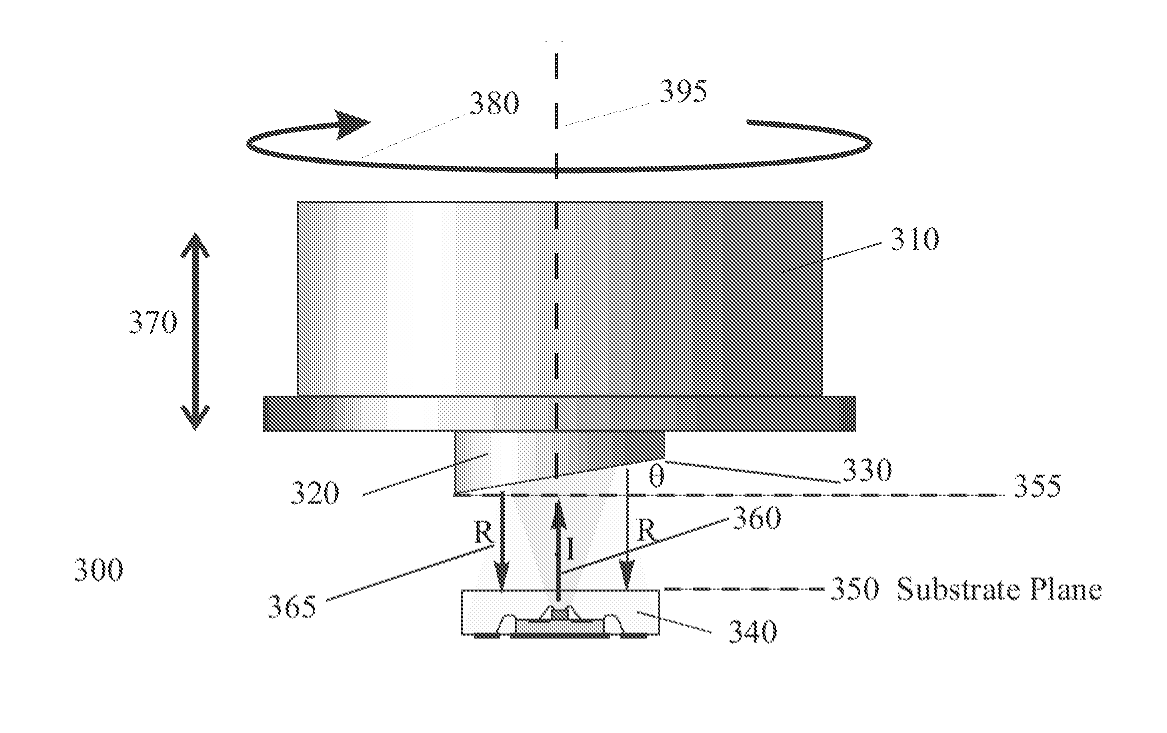
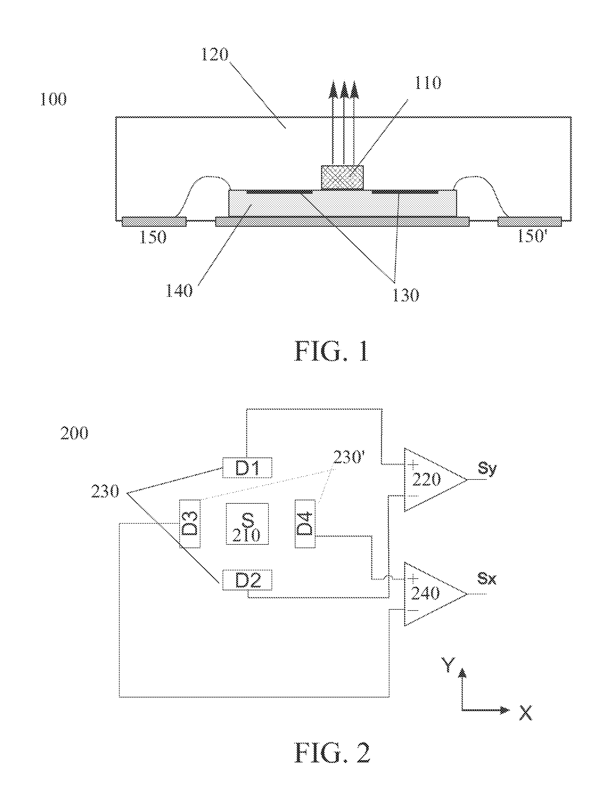
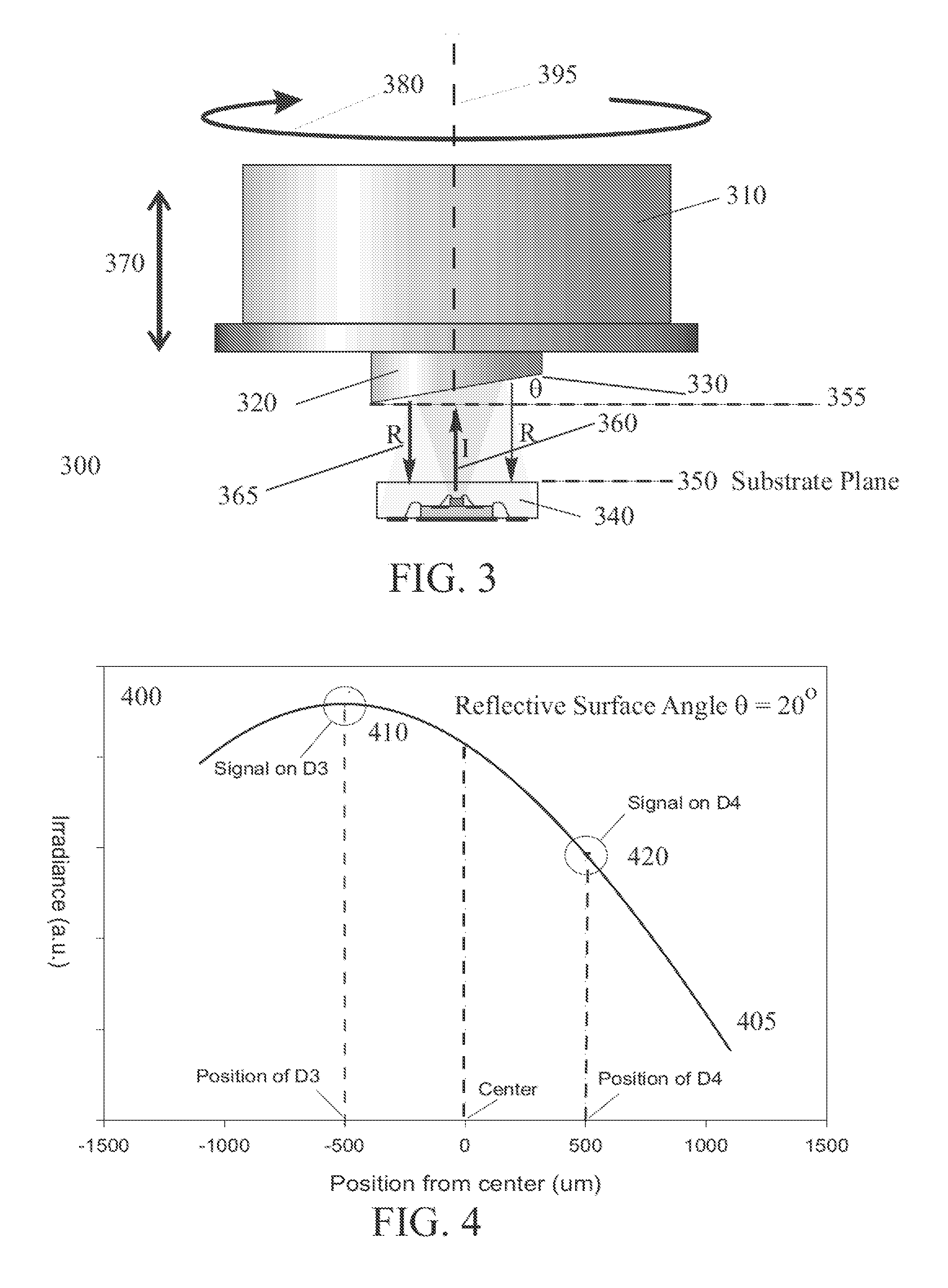
[0022]The substrate includes a plurality of photo detectors arranged around a light source. The substrate that contains the photo detectors may also contain an integrated circuit for control and signal processing. When used in applications, a rotation shaft with a flat and polished end is placed in the vicinity of a sensor module. The polished end acts as a mirror. The surface of the reflector is slightly slanted with respect to the perpendicular cross-section of the shaft. Light comes from the light source, is reflected by the mirror and creates a light spot on the photo detectors. Light irradiance has an asymmetric distribution over the photo detectors, thus creating differential signals on the output of the pro...


PUM


Abstract

In an example embodiment, a system detects the degree of rotation of a knob, the system comprises a shaft having a length and a first end and a second end; the second end has an oblique reflective surface defined thereon; the first end fixedly attached to the knob. Containing the shaft is a rotation body, having a receptacle to accommodate the second end of the shaft with the oblique reflective surface exposed. An integrated circuit optical module is optically coupled the rotation body and the optical module detects light irradiance profile from the oblique reflective surface. The optical module includes a solid state light source and a plurality of photo detectors which generate an electrical signal upon exposure to light. As the knob is rotated, the oblique reflective surface generates a changing asymmetric irradiance profile, the change being translated into an electrical signal via the photo detectors. The electrical signal corresponds to the degree of rotation of the knob.

Description

FIELD OF INVENTION[0001]This invention relates to user interface devices. More particularly, this invention relates to an optical sensor device to measure the mechanical rotation and the rotational speed of a shaft. This shaft may be part of a dial or knob assembly in an electronic apparatus.BACKGROUND[0002]The world finds a myriad of electronic devices available to the user. For the user to take advantage of what a particular device has to offer, he must be able to interface with it. On such interface is the knob, found on practically every mechanical or electronic device. People learn to use this interface at an early age and quickly associate the turning of the knob as changing how the device operates—for instance, turn the knob clockwise to go to “high” and turn the knob counter-clockwise to go to “low.” As in the case of a radio, the knob may be attached to a potentiometer; the user turns up the volume and the resistance of the potentiometer decreases, so that more of the outpu...

Claims


Application Information

Patent Timeline
Patent Type & Authority Applications(United States)
IPC IPC(8): G01D5/30G01D5/34
CPCG01D5/285G01D5/3473G01D5/30G01P3/36G06F3/0312H01H25/06G06F3/0362
Inventor PHAN LE, KIM
Owner NXP BV
Why Eureka
Try Eureka