Indicator position detecting device and indicator position detecting method

a technology of position detection and indicator, which is applied in the direction of static indicating devices, resistance/reactance/impedence, instruments, etc., can solve the problems of long detection time of all cross-points, noise included in the signal detected by the receiving conductor group, etc., and achieve the effect of high speed

Active Publication Date: 2011-10-06
WACOM CO LTD
View PDF5 Cites 22 Cited by
  • Summary
  • Abstract
  • Description
  • Claims
  • Application Information

AI Technical Summary

Benefits of technology

[0042]In the present invention, the plurality of signals with different frequencies are simultaneously supplied to the plurality of conductors on the transmission side, and frequency analysis of signals from the respective receiving conductors is carried out to thereby detect the position of the indicator on the conductor pattern on the reception side. Due to this configuration, the position detection processing at a plurality of cross-points can be simultaneously executed for each receiving

Problems solved by technology

In the conventional indicator position detecting device of the capacitive coupling system of the cross-point type like the above-described device, noise included in the signal detected by the receiving conductor group often becomes a problem.
Furthermore, in the indicator position detecting device of this kind, the position detection processing for the respective cross-points is sequentially e

Method used


Image

  • Indicator position detecting device and indicator position detecting method
  • Indicator position detecting device and indicator position detecting method
  • Indicator position detecting device and indicator position detecting method

Examples


first embodiment

2. FIRST EMBODIMENT

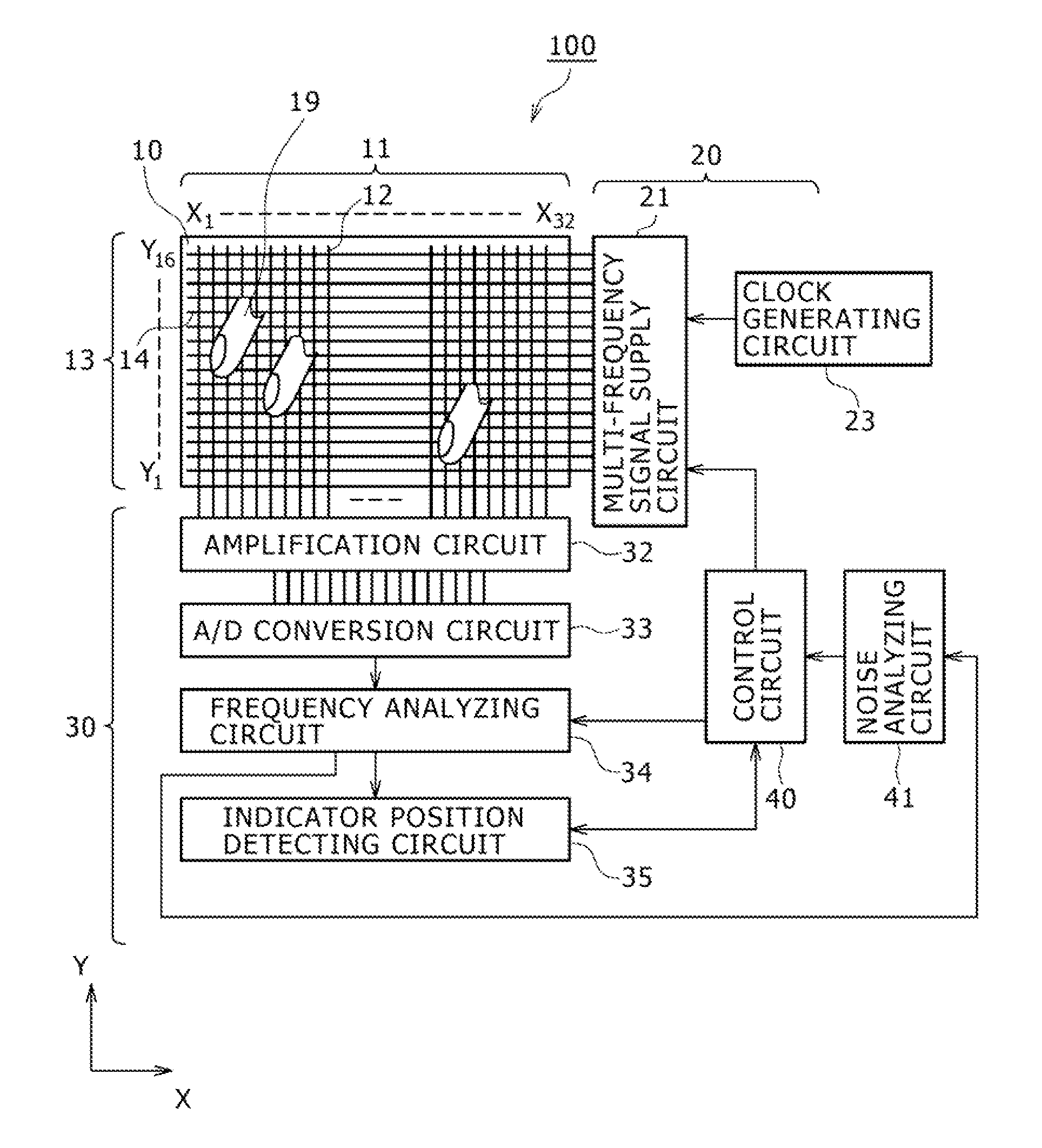
[0126]Next, with reference to FIG. 7 to FIG. 10, an example of the first embodiment of the present invention will be described. The part common to the already-described indicator position detecting device 100 with the configuration of FIG. 1 and so forth is given the same symbol and description thereof is omitted. The example of the first embodiment of the present invention has characteristics in configuration and processing, to switch (change) the frequency of the signal supplied from the multi-frequency signal supply circuit 21 to the transmitting conductor 14 on the side of the transmission part 20 and to switch (change) the frequency of the signal received from the receiving conductor 12 on the side of the reception part 30.

[0127]For example, in the case of employing a configuration in which signals of 16 kinds of frequencies are simultaneously supplied to the transmitting conductors, generation of signals of 32 kinds of frequencies, which is twice 16, is allo...

second embodiment

3. SECOND EMBODIMENT

[0150]Next, an example of a second embodiment of the present invention will be described with reference to FIG. 11 and FIG. 12. As the basic configuration of the indicator position detecting device 100, the configuration described with FIG. 1 to FIGS. 6A to 6C is employed. The present embodiment has characteristics in the configuration of a multi-frequency signal supply circuit 211 shown in FIG. 11 and detection thereof.

[0151]In FIG. 11, the multi-frequency signal supply circuit 211 simultaneously supplies signals of plural frequencies to the respective transmitting conductors 14 making up the sensor part 10. Here, while the example of FIG. 7 is the configuration in which a signal of a frequency in the first group or a frequency in the second group is selectively supplied to each transmitting conductor, the multi-frequency signal supply circuit 211 shown in FIG. 11 has a configuration in which a signal of a frequency in the first group and a signal of a frequency...

third embodiment

4. THIRD EMBODIMENT

[0161]Next, an example of a third embodiment of the present invention will be described with reference to FIG. 13 and FIG. 14. As the basic configuration of the indicator position detecting device 100, the configuration described with FIG. 1 to FIGS. 6A to 6C is employed. The present embodiment has characteristics in the configuration of a multi-frequency signal supply circuit 221 shown in FIG. 13 and detection thereof.

[0162]The multi-frequency signal supply circuit 221 shown in FIG. 13 supplies signals of predetermined frequencies to the transmitting conductors 14 similarly to the example of FIG. 1. In FIG. 7, the configuration is shown in which the signal of a predetermined frequency is selected from a frequency in the first group and a frequency in the second group depending on the state of noise and supplied to the corresponding transmitting conductor. In the multi-frequency signal supply circuit 221 shown in FIG. 13, signals of a predetermined number of spare...


PUM


Abstract

An indicator position detecting device and method are provided, which allow accurate position detection without the influence of noise in detection of the position of an indicator (e.g., a finger, a stylus pen) by a capacitive coupling system. To a conductor pattern in which plural conductors for signal transmission and plural conductors for signal reception intersect with each other, signals with frequencies different from each other are simultaneously supplied to the plural conductors on the transmission side, and signals of respective frequencies corresponding to the plural signals with the different frequencies are detected on the reception side, to thereby detect the position of an indicator on the conductor pattern. The amount of noise of each of the detected frequencies is detected. Any frequency that cannot be properly detected due to noise is switched to another frequency, and detection is carried out based on the newly selected frequency.

Description

CROSS-REFERENCE TO RELATED APPLICATION [0001]The present application claims priority under 35 U.S.C. §119(a) of Japanese Application No. 2010-077141, filed Mar. 30, 2010, the entire content of which is incorporated herein by reference.TECHNICAL FIELD [0002]The present invention relates to an indicator position detecting device and an indicator position detecting method, and more specifically relates to an indicator position detecting device and an indicator position detecting method for detecting the position of an indicator by an capacitive coupling system.BACKGROUND ART [0003]Conventionally, as the system for detecting the position of an indicator, such as a finger and a dedicated pen, used for a touch panel etc., various systems such as a resistive film system and an capacitive coupling system (capacitance system) have been proposed, for example. Among them, an indicator position detecting device of the capacitive coupling system is being actively developed in recent years.[0004]...

Claims


Application Information

Patent Timeline
IPC IPC(8): G01R23/02
CPCG06F3/044G06F3/0418G06F3/0446G06F3/04182G06F3/04166
Inventor ODA, YASUO
Owner WACOM CO LTD
Why Eureka
Try Eureka