Driving condition evaluation device and evaluation method

a condition evaluation and condition technology, applied in the direction of instruments, analogue processes for specific applications, electric/magnetic computing, etc., can solve the problems of affecting the fuel consumption that cannot be reflected, and the abrupt acceleration of fuel degradation cannot be sufficiently suppressed

a condition evaluation and condition technology, applied in the direction of instruments, analogue processes for specific applications, electric/magnetic computing, etc., can solve the problems of affecting the fuel consumption that cannot be reflected, and the abrupt acceleration of fuel degradation cannot be sufficiently suppressed

US20110241865A1Active Publication Date: 2011-10-06TOYOTA JIDOSHA KK

Image

  • Driving condition evaluation device and evaluation method
  • Driving condition evaluation device and evaluation method
  • Driving condition evaluation device and evaluation method

Examples


Embodiment Construction

[0019]Hereinafter, with reference to the drawings, an embodiment of the invention will be explained.

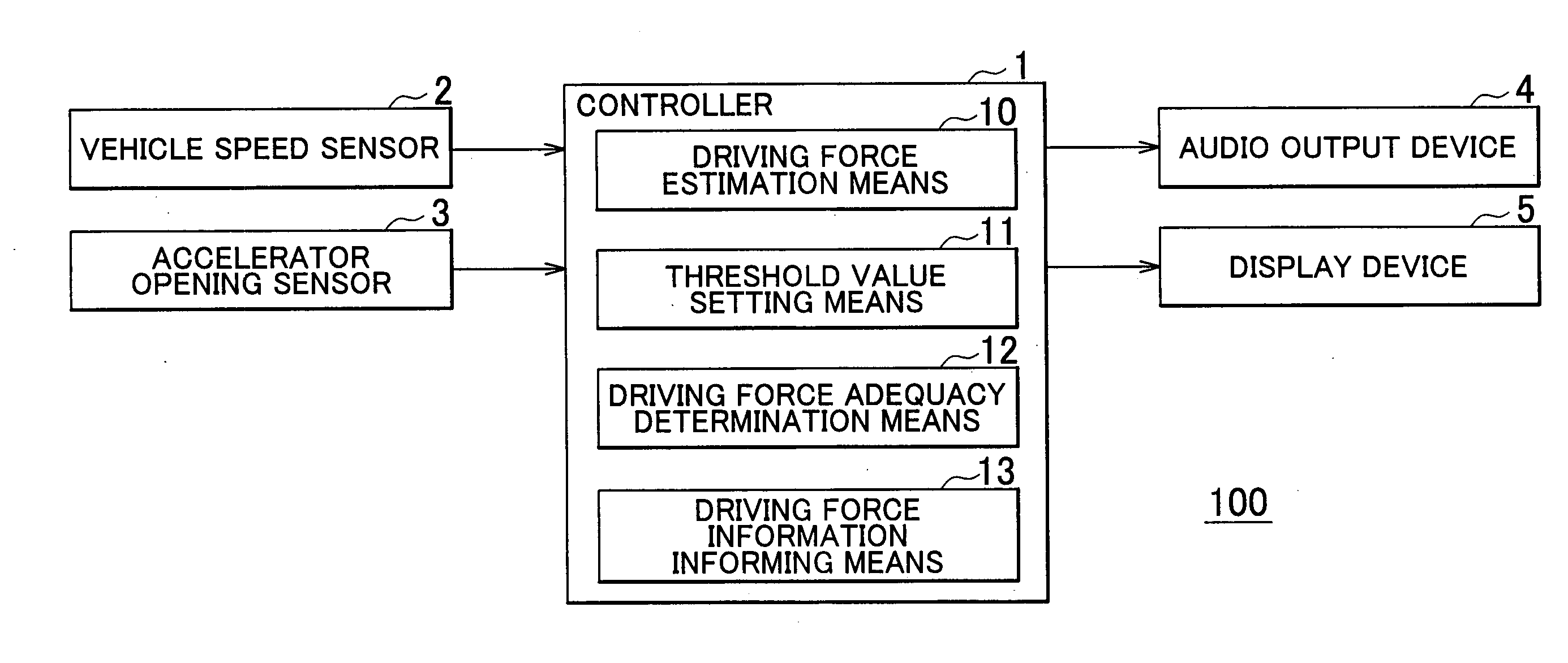
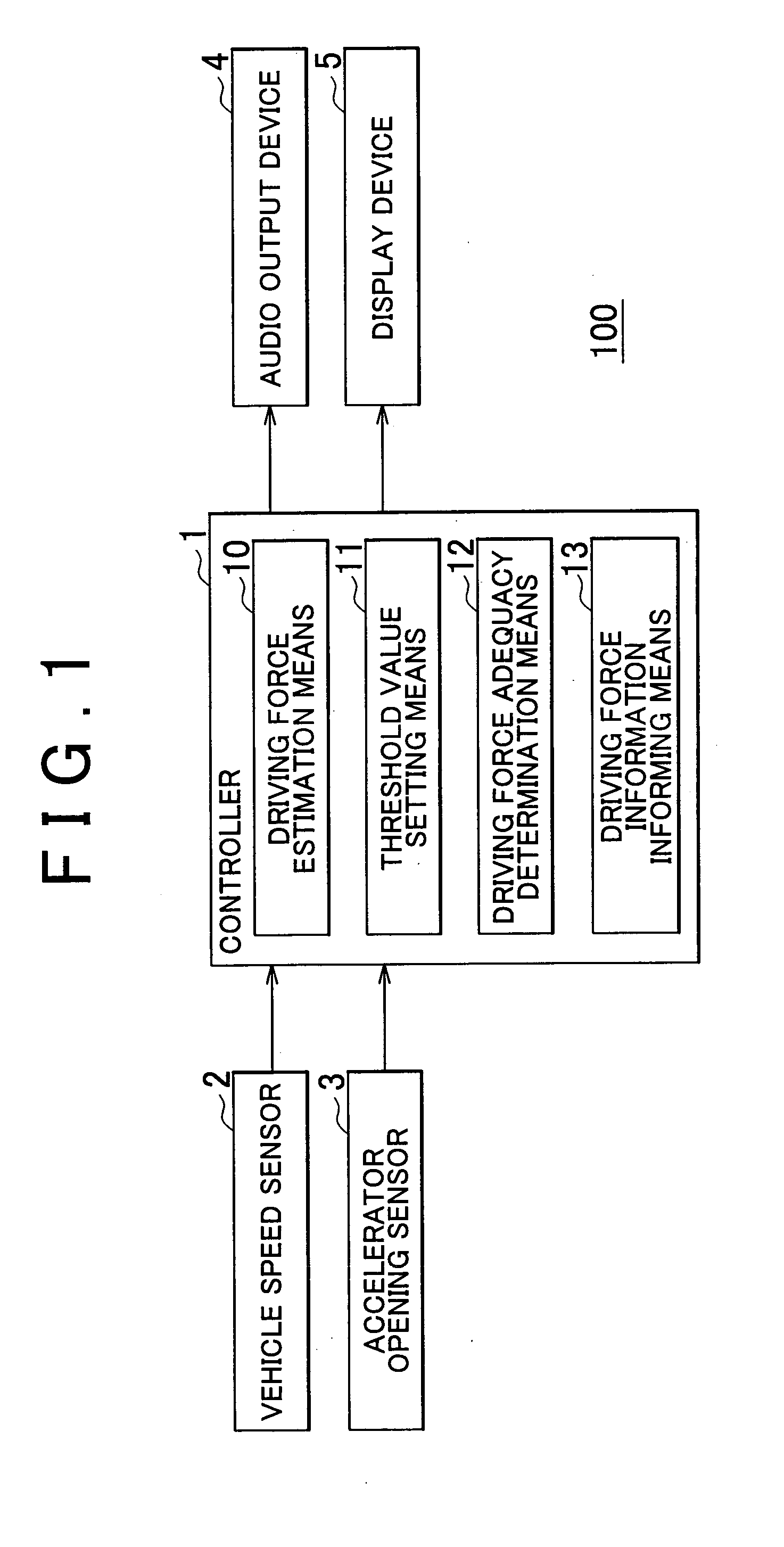
[0020]FIG. 1 is a block diagram showing a configuration example of a driving condition evaluation device according to an embodiment of the invention. This driving condition evaluation device 100 is an in-vehicle device that achieves suppression of fuel consumption degradation by informing a driver of an evaluation of a driving condition performed by using driving force as a criterion. The driving condition evaluation device 100 includes a controller 1. The controller 1 receives an input from a vehicle speed sensor 2 and an accelerator opening sensor 3, and outputs a control signal to an audio output device 4 and a display device 5. These components are coupled via an in-vehicle LAN such as a controller area network (CAN), a local interconnect network (LIN), or the like.

[0021]The controller 1 is a computer provided with a central processing unit (CPU), a random access memory (RAM), a r...


PUM


Abstract

A driving condition evaluation device is provided. The device includes a vehicle speed detection portion configured to detect a vehicle speed. A driving force estimation portion is configured to estimate driving force for driving a vehicle generated in accordance with a driving operation performed by a driver. A threshold value setting portion is configured to set a threshold value of the driving force based on the vehicle speed detected by the vehicle speed detection portion. A driving force information informing portion is configured to inform the driver of a relationship between the driving force estimated by the driving force estimation portion and the threshold value set by the threshold value setting portion.

Description

[0001]The invention relates to a driving condition evaluation device and evaluation method for evaluating a driving condition of a vehicle and, more particularly, to a driving condition evaluation device that achieves prevention of fuel consumption degradation by informing the driver of the vehicle of an evaluation of a driving condition.[0002]Generally, although acceleration of vehicles driving on a public road is large during driving at low speed and is small during driving at high speed, acceleration necessary to realize normal driving falls within a certain range. Informing drivers that acceleration departing from such a certain range leads to fuel consumption degradation is desirable in view of an efficient use of energy and protection of global environment.[0003]Under these circumstances, an accelerator opening display device for indicating an accelerator opening so as not to deviate from a fuel-efficient operation area is known (see, for example, Japanese Patent Application P...

Claims


Application Information

Patent Timeline
06 Oct 2011
Publication
US20110241865A1
IPC
B60Q1/00; B60R16/02; B60W40/105; B60W50/14; B60W50/16
CPC
B60W50/14; B60W50/08; B60R16/023
Inventors
SAITO, KAN