Liquid ejection apparatus

a liquid ejection and ejection tube technology, applied in the field of recording devices, can solve the problems of wear sensor inability to properly detect the mark, and inability to eliminate the problem of the protective layer and the mark wear

Active Publication Date: 2011-10-06
BROTHER KOGYO KK
View PDF5 Cites 19 Cited by
  • Summary
  • Abstract
  • Description
  • Claims
  • Application Information

AI Technical Summary

Benefits of technology

[0006]According to the known technology, the position detection mark is provided on the inner circumferential surface of the conveyance belt, and hence the mark may be worn out due to repeated contact with a roller. This causes a problem in that the sensor cannot properly detect the mark. To solve this problem, a protective layer is provided to cover the position detection mark. This, however, does not eliminate the problem of the wear of the protective layer and the mark.

Problems solved by technology

According to the known technology, the position detection mark is provided on the inner circumferential surface of the conveyance belt, and hence the mark may be worn out due to repeated contact with a roller.
This causes a problem in that the sensor cannot properly detect the mark.
This, however, does not eliminate the problem of the wear of the protective layer and the mark.

Method used


Image

  • Liquid ejection apparatus
  • Liquid ejection apparatus
  • Liquid ejection apparatus

Examples


first embodiment

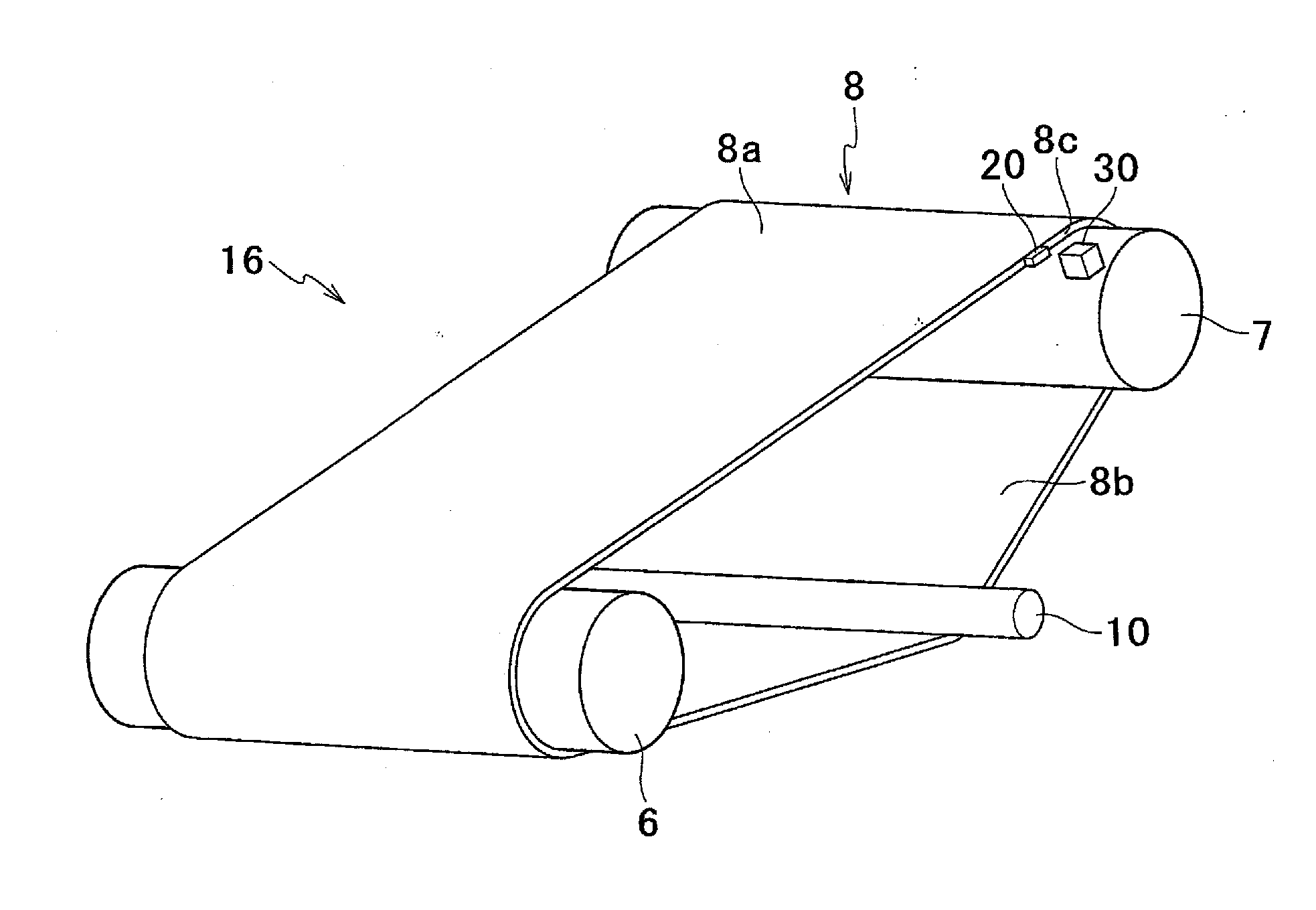
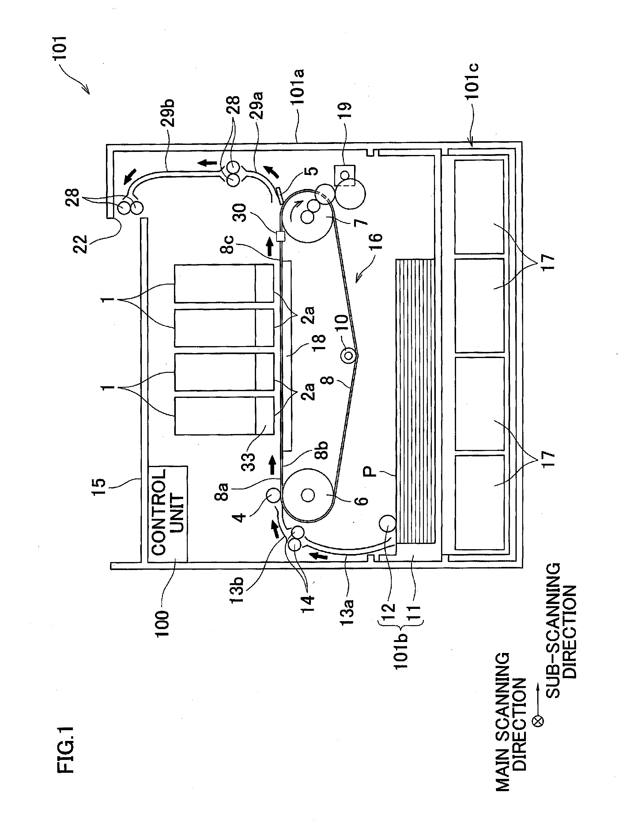
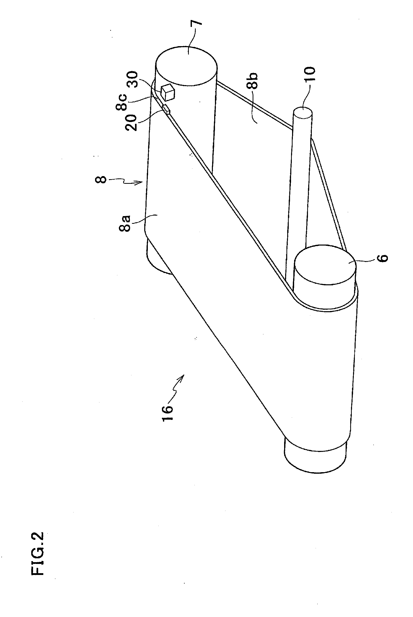
[0022]As shown in FIG. 1, an inkjet printer 101 of First Embodiment has a rectangular parallelepiped chassis 101a. In the chassis 101a are provided four inkjet heads 1 (record heads; hereinafter, heads 1) ejecting magenta, cyan, yellow, and black inks, respectively, and a conveyance mechanism 16. On the inner surface of the top plate of the chassis 101a, a control unit 100 is attached to control the operations of components such as the heads 1 and the conveyance mechanism 16. The upper surface of the top plate functions as a sheet discharge portion 15 to which sheets P with images are discharged. Below the conveyance mechanism 16 is provided a sheet supply unit 101b to be detachable to the chassis 101a. Below the sheet supply unit 101b is provided an ink tank unit 101c to be detachable to the chassis 101a.

[0023]Inside the inkjet printer 101, a conveying path is formed along the thick arrows in FIG. 1. On this conveying path, sheets P are conveyed from the sheet supply unit 101b tow...

second embodiment

[0053]Now, referring to FIGS. 6 to 10, Second Embodiment which is a modification of the embodiment above will be described. It is noted that the same components as in the embodiment above are denoted by the same reference numerals as in the embodiment, and the description thereof will be omitted.

[0054]An inkjet printer 201 of Second Embodiment further includes a belt position sensor 25 which detects the position of the belt 8 in the axial directions of the belt roller 7, i.e. the directions in which the profile 8c of the belt 8 approaches and is distanced from the light emitting element 30a. As shown in FIG. 7, the belt 8 is capable of traveling to, for example, a position indicated by the broken line L and a position indicated by the broken line R, in the axial direction of the belt roller 7. In other words, the belt 8 is capable of traveling in the directions in which the profile 8c of the belt 8 and the light emitting element 30a of the mark sensor 30 get close to each other and ...

third embodiment

[0076]Now, referring to FIGS. 11 and 12, Third Embodiment which is a modification of the embodiments above will be described. It is noted that the same components as in the embodiments above are denoted by the same reference numerals as in the embodiments, and the description thereof will be omitted.

[0077]As shown in FIG. 11, in a control unit 300 of an inkjet printer 301 according to Third Embodiment are provided a storage unit 48, an expected signal value deriving unit 50, a third determining unit 49, and a light quantity adjustment unit 146, in addition to the conveyance controller 40, the unit 41, and the second determining unit 45.

[0078]The storage unit 48 stores sensor property information indicating changes in the detected signal value output from the light receiving element 30b in accordance with positional changes of the belt 8 and with changes in the quantity of light from the light emitting element 30a. Although FIG. 8 shows only the curve A in the case of the predetermin...


PUM


Abstract

A recording apparatus includes a recording unit recording an image, an endless belt which is stretched between rollers such that the inner circumferential surface thereof contacts the rollers and the outer circumferential surface thereof opposes the recording unit, a mark arranged on the profile of the belt, and a mark detection unit which detects that the mark moving in accordance with the travel of the belt is positioned at a predetermined position.

Description

CROSS REFERENCE TO RELATED APPLICATION[0001]The present application claims priority from Japanese Patent Application No. 2010-83225, which was filed on Mar. 31, 2010, the disclosure of which is herein incorporated by reference in its entirety.BACKGROUND OF THE INVENTION[0002]1. Field of the Invention[0003]The present invention relates to a recording apparatus having a mark used for detecting a predetermined position on a conveyance belt conveying a recording medium.[0004]2. Description of the Related Art[0005]Known technologies are arranged such that a predetermined position on a conveyance belt conveying sheets is detected in order to fix a region where ink is ejected when flushing is carried out. For example, according to a known technology, a position detection mark is provided on the inner circumferential surface of the conveyance belt, and a position on the conveyance belt is detected by detecting the mark by means of a sensor which is provided at a region where the mark passes...

Claims


Application Information

Patent Timeline
Patent Type & Authority Applications(United States)
IPC IPC(8): B41J29/38
CPCB41J11/007
Inventor OTOBE, MUTSUMI
Owner BROTHER KOGYO KK
Why Eureka
Try Eureka