
Cement mixing pile construction method

A technology of cement mixing piles and construction methods, which is applied to sheet pile walls, foundation structure engineering, construction, etc., can solve problems affecting the service life of drill pipes, difficulty in cement mixing piles, and extended construction period, achieving remarkable treatment effects and improving Construction efficiency and the effect of reducing drill pipe wear

Pending Publication Date: 2021-12-31
NO 1 CONSTR ENG CO LTD OF GUIZHOU CONSTR & ENG GRP
View PDF4 Cites 0 Cited by
  • Summary
  • Abstract
  • Description
  • Claims
  • Application Information

AI Technical Summary

Problems solved by technology

In the prior art, the patent document with the publication number "CN108914929A" discloses a construction method for cement mixing piles, which includes the following steps: measuring and setting out, mechanical positioning and centering, pre-stirring and sinking, preparing cement slurry, spraying Slurry, mixing, lifting, repeated mixing, cleaning equipment, pipelines, displacement, adopting the technical solution disclosed in this patent document, to a certain extent, links the construction problems of cement mixing piles. However, in actual engineering, cement mixing piles The setting area is often faced with complex geological conditions. The underground soil is often combined with soft soil layers and hard soil layers. It is difficult for the drill pipe to drill into the soil, and after the cement slurry is injected into the underground soil, the solidification speed of the cement slurry is subject to the ambient temperature and the temperature of the underground soil, and the solidification speed is slow, which makes it difficult for the cement mixing pile to be completed within the scheduled construction period. To achieve the expected strength within the time frame, the construction period had to be extended

Method used


Image

  • Cement mixing pile construction method

Examples


Embodiment Construction

[0024] The technical solution of the present invention is further described below, but the scope of protection is not limited to the description.

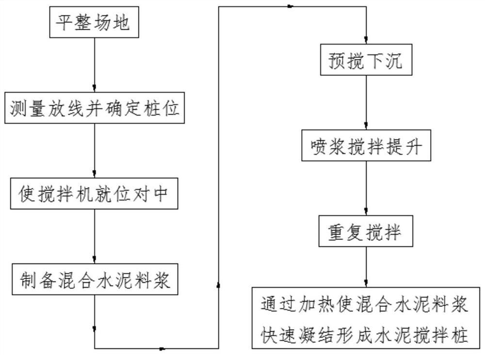
[0025] Such as figure 1 Shown, the invention provides a kind of cement mixing pile construction method, comprises the following steps:

[0026] Step 1: Measurement and setting out: carry out measurement and setting out according to the design drawings and review, and determine the pile position;

[0027] Step 2: Mechanical alignment: provide a mixer, the mixer includes a drill pipe, a collecting hopper and a liquid storage tank, the drill pipe and the collecting hopper are connected through a mortar pump, the drill pipe and the liquid storage tank are connected through a feed pump, and the mixer is moved to step 1 Center the pile position, align the drill pipe with the pile position, and the centering error is not greater than 50mm;

[0028] Step 3: Prepare mixed cement slurry: Mix 42.5# ordinary Portland cement, heat conduction ...


PUM


Abstract

The invention provides a cement mixing pile construction method. The cement mixing pile construction method comprises the following steps: leveling a site; carrying out surveying and setting out, and determining a pile position; positioning and centering a stirrer; preparing mixed cement slurry: carrying out pre-stirring and sinking: spraying slurry, and performing stirring and lifting; repeatedly stirring; and enabling the mixed cement slurry to realize rapid setting through heating to form a cement mixing pile. According to the technical scheme, the lubricating liquid is injected into the underground soil body in the pre-stirring sinking stage, the lubricating liquid plays a role in lubricating and cooling a drill rod, abrasion of the drill rod is reduced, the service life of the drill rod is prolonged, the lubricating liquid further infiltrates the underground soil body, drilling of the drill rod is easier, the construction progress is accelerated, and the construction period is shortened; and heat conduction wires are mixed in the mixed cement slurry, the top face of the cement mixing pile is heated after initial setting forming of the cement mixing pile, the setting forming process of the cement mixing pile is accelerated, all components in the cement mixing pile are tightly connected and rapidly set to the expected strength, the construction period is shortened, and the construction efficiency is improved.

Description

technical field [0001] The invention belongs to the technical field of construction engineering, and in particular relates to a construction method of a cement mixing pile. Background technique [0002] Cement mixing piles are an effective form of soft soil treatment, and the applicable soil layers include silt, muddy soil, silt, cohesive soil and miscellaneous fill. The method adopted by the cement mixing pile is to use cement as the main agent of the curing agent, and use the mixing pile machine to spray the cement into the soil and stir it fully, so that a series of physical and chemical reactions between the cement and the soil will occur, and the silt will harden to improve the strength of the foundation. Over the years of development, cement mixing piles have become more and more widely used in soft soil foundation treatment and the technology has become more and more mature. In the prior art, the patent document with the publication number "CN108914929A" discloses a ...

Claims


Application Information

Patent Timeline
Patent Type & Authority Applications(China)
IPC IPC(8): E02D5/46
CPCE02D5/46
Inventor 何家亮袁肖何传志姜成姜坤刘璇左海宏周雨婷覃鹤张思斌赵红霞
Owner NO 1 CONSTR ENG CO LTD OF GUIZHOU CONSTR & ENG GRP
Learn More