Turbine air-floatation main shaft

An air-floating spindle and air-floating bearing technology, applied in the field of energy and power, can solve the problems of limited application, poor natural heat dissipation conditions, thermal displacement of the shaft body and the shell, etc., and achieve high energy utilization rate, long working life, and stable rotation smooth effect

Inactive Publication Date: 2012-08-08
SHENZHEN GRADUATE SCHOOL TSINGHUA UNIV
View PDF6 Cites 13 Cited by
  • Summary
  • Abstract
  • Description
  • Claims
  • Application Information

AI Technical Summary

Problems solved by technology

[0003] However, since the motor of the electric spindle is located in the spindle unit, the natural heat dissipation conditions are poor. During the high-speed operation of the motor, the heat generated by the internal power loss of the motor and the heat generated by the friction of the high-speed bearings are easily transmitted to the shaft body and The thermal displacement of the shaft body and the housing in the housing directly affects the performance of the spindle
Moreover, the common lubrication methods for electric spindles are oil mist lubrication and oil-air lubrication. In oil mist lubrication, the lubricating oil is dispersed into a mist by impact in the mixing chamber, mixed with air, and then enters the bearing. A large amount of oil mist is also carried out, causing pollution; oil-air lubrication is still in its infancy in the domestic machine tool industry, how to select oil-air lubrication parameters (including air pressure, air flow, lubricating oil volume, lubricating oil viscosity, additives types and addition ratios, etc.) to achieve the best lubrication and cooling effect, there is no relatively mature experience in China
In addition, since the electric spindle works under high-frequency and narrow-wave conditions, a strong induced current is usually generated in its casing, so it is necessary to use a special dipping process and a method of grounding the casing to shield the stator, which increases the complexity of the mechanism
Due to the many defects of the electric spindle, its application in some fields is limited

Method used


Image

  • Turbine air-floatation main shaft
  • Turbine air-floatation main shaft
  • Turbine air-floatation main shaft

Examples


Embodiment Construction

[0024] The principle, structure and working process of the present invention will be further described through the embodiments below in conjunction with the accompanying drawings.

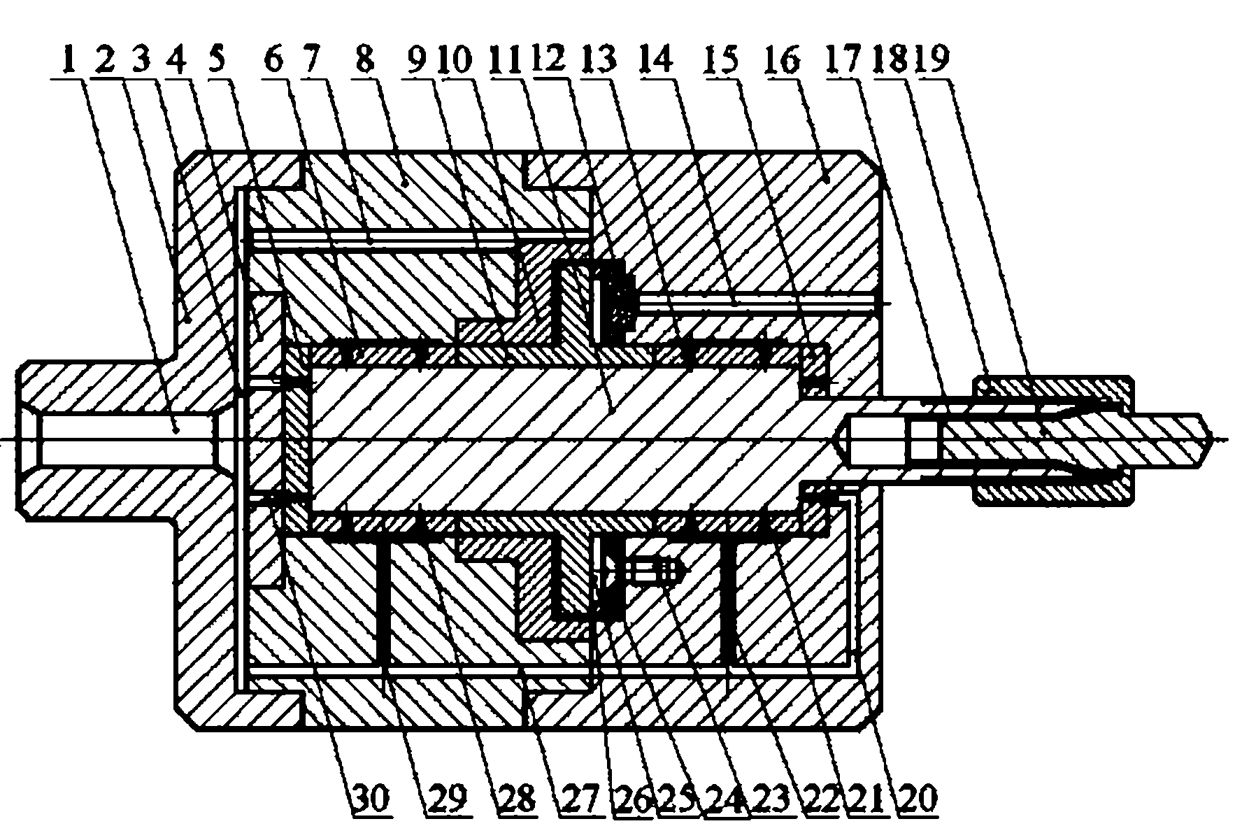
[0025] refer to figure 1 , the turbine air-floating main shaft includes a shell that runs through the first end of the shell (ie figure 1 The shaft body 11 of the right end in), and the pneumatic turbine.

[0026] The casing is composed of an annular turbine base 8, a first end cover 2 connected to the first end of the turbine base 8, and a second end cover 16 connected to the second end of the turbine base 8. The second end cover 16 constitutes At the first end of the housing, an air cavity 3 is provided between the first end cover 2 and the first end of the turbine base 8, and the first end cover 2 is provided with an air inlet 1 communicating with the air cavity 3. Several exhaust holes 14 are arranged on the two end covers 16, and some exhaust holes 14 are preferably evenly distributed around...


PUM


Abstract

The invention discloses a turbine air-floatation main shaft. The turbine air-floatation main shaft comprises a shell and a shaft body penetrating through a first end part of the shell, wherein the shell comprises a ring-shaped turbine base, a first end cover and a second end cover; the first end cover is connected with a first end of the turbine base and is provided with an air inlet hole; the second end cover is connected with a second end of the turbine base and is provided with a plurality of exhaust holes; the first end part of the shell is formed by the second end cover; an air cavity is formed between the first end cover and the first end of the turbine; a pneumatic turbine machine is arranged in an inner cavity of the shell and at the middle part of the shaft body; air-floatation bearings are arranged at the other positions around the shaft body; a turbine stator and a turbine rotor of the pneumatic turbine machine are correspondingly and fixedly connected with the turbine base and the shaft body; the turbine base and the second end cover are internally provided with bearing air passages communicated with the air cavity; and the turbine base is also internally provided with a plurality of turbine air passages communicated with the air cavity. The turbine air-floatation main shaft disclosed by the invention has the advantages of simple and compact structure, high efficiency and rotating speed, smoothness in rotation, no wear, no need of adding lubricating oil inside and long working life.

Description

technical field [0001] The invention relates to a high-speed spindle, in particular to an air-floating spindle that utilizes the principle of fluid statics to stabilize the shaft on non-contact support, and belongs to the technical field of energy and power. Background technique [0002] As one of the advanced manufacturing technologies, high-speed machining has been widely used in various industries, especially aerospace, automotive industry, PCB drilling and mold processing. At present, the commonly used high-speed spindles are divided into two types in structure, namely, separate high-speed spindles and built-in electric spindles (also known as electric spindles). The separated high-speed spindle drives the shaft body to rotate through the middle transmission device (such as belts, gears, etc.) to work. Due to the influence of its transmission mechanism, the increase of the spindle speed is limited to a certain extent. The electric spindle is to place a high-speed motor ...

Claims


Application Information

Patent Timeline
Patent Type & Authority Applications(China)
IPC IPC(8): B23B19/02
Inventor 夏必忠叶佩青汪劲松张辉王殿新聂权刘建春
Owner SHENZHEN GRADUATE SCHOOL TSINGHUA UNIV
Why Eureka
Try Eureka