Fixing mechanism of optical scanning device and image forming apparatus

a technology of optical scanning and fixing mechanism, which is applied in the direction of lighting support devices, washstands, instruments, etc., can solve the problems of deteriorating printing quality, significant, and inability to prevent the housing from deformation, so as to prevent the print quality from deteriorating, improve the operability of the assembling process of the optical scanning device, and prevent the effect of deteriorating the quality of the prin

Active Publication Date: 2011-10-06
KYOCERA DOCUMENT SOLUTIONS INC
View PDF1 Cites 12 Cited by
  • Summary
  • Abstract
  • Description
  • Claims
  • Application Information

AI Technical Summary

Benefits of technology

[0013]According to the present invention, a position of a housing is determined, and the housing is supported by penetrating a protruding pin through a penetration hole, and, in this condition, the housing is biased in one direction by a biasing part. In other words, according to the present invention, the housing is not fixed rigidly to the frame. When a force is applied, which exceeds a biasing force received by the housing from the biasing part, a deformation of the housing or a change in the position of the housing are allowed.
[0014]Therefore, according to the present invention, a localized heat deformation does not occur on the housing. Therefore, a deviation in the position of the scanning line does not occur. Further, it is possible to prevent the print quality from deteriorating.
[0015]Moreover, according to the present invention, the position of the housing is determined, and the housing is supported by the biasing part biasing the housing in one direction. Therefore, when the housing is placed at an approximate position at the time of assembly, thereafter, the position of the housing may be determined precisely by the biasing force of the biasing part. Further, since the housing is not fixed rigidly to the frame, the housing may be easily detached as well.
[0016]Therefore, according to the present invention, the operability of an assembling process of the optical scanning device is improved, so that a user may exchange the optical scanning device on his or her own without relying on a staff member with specialized technical knowledge.

Problems solved by technology

Therefore, it is not possible to prevent the housing from deforming due to the heat generated by the heat generating part.
When a deformation due to heat cannot be released due to the housing being completely screw-fastened to the frame, a significant, localized heat deformation occurs.
When such a heat deformation occurs on the housing, the location of the scanning line may deviate, thereby causing a deterioration in the quality of printing.
As a result, the assembling operation cannot be performed efficiently.
Further, there is a problem in that a staff member with specialized technical knowledge is required in order to exchange the optical scanning device.

Method used


Image

  • Fixing mechanism of optical scanning device and image forming apparatus
  • Fixing mechanism of optical scanning device and image forming apparatus
  • Fixing mechanism of optical scanning device and image forming apparatus

Examples


first embodiment

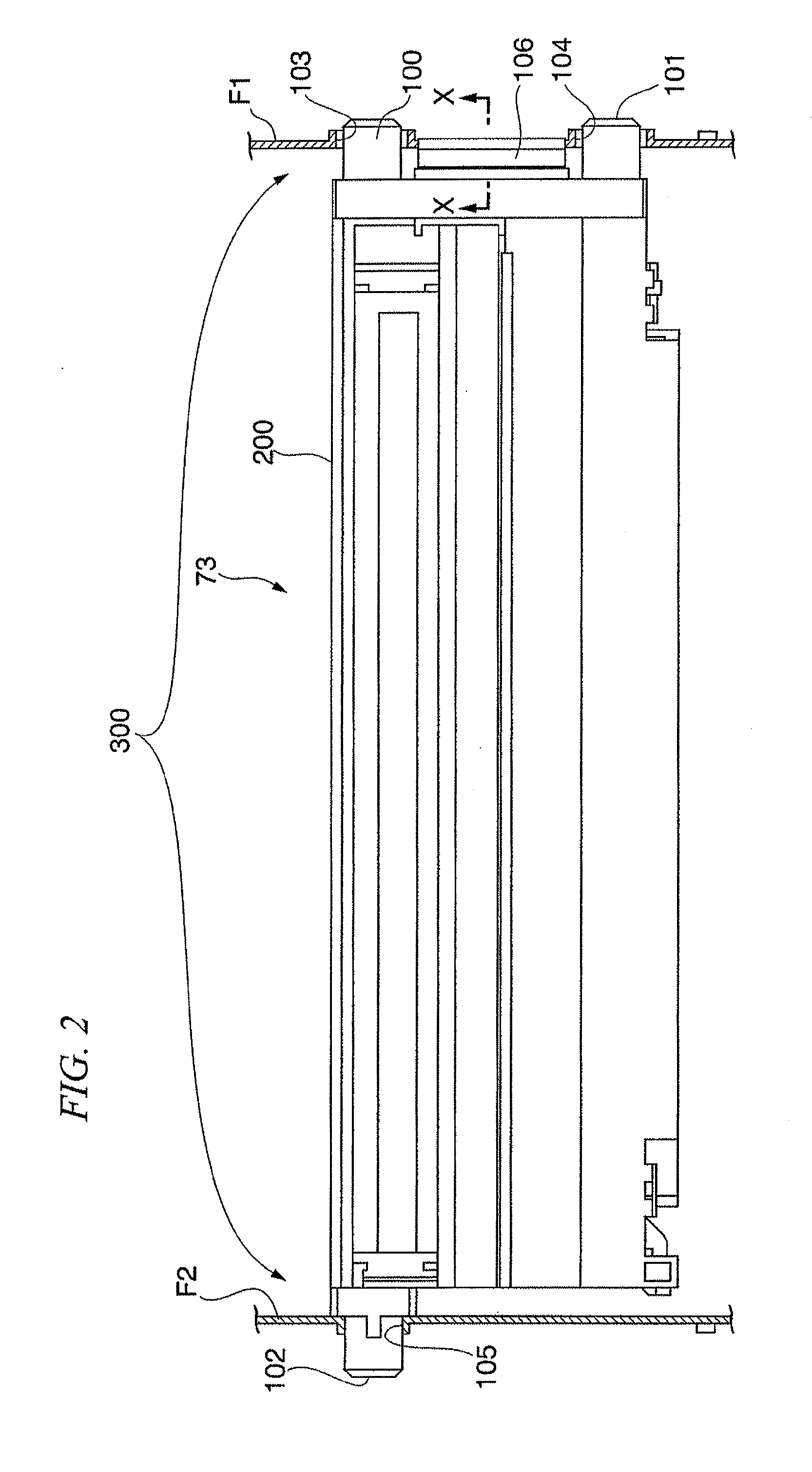
[0023]Hereinafter, a first embodiment of a fixing mechanism of an optical scanning device and an imaging forming apparatus according to the present invention is described with reference to the diagrams. In the drawings referred to below, the scaling of each component is changed as appropriate so that each component becomes a size which may be recognized. Further, in the description below, a copying machine is provided and described as an example of an image forming apparatus according to the present invention.

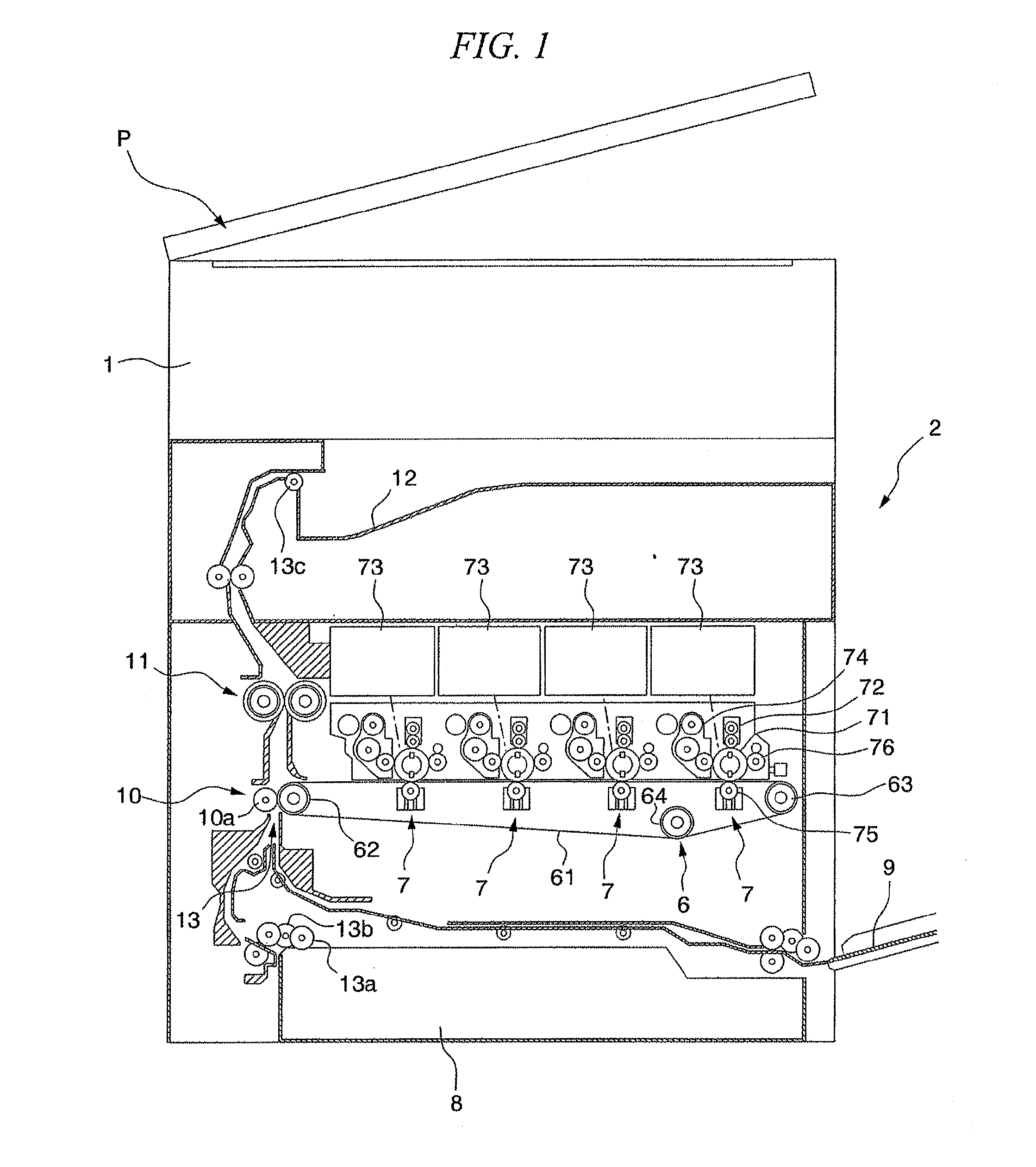
[0024]FIG. 1 is a cross sectional diagram showing a skeletal configuration of a copying machine P according to the present embodiment. As shown in this diagram, the copying machine P according to the present embodiment comprises an image reading part 1, which reads an image of a draft, and a printing part 2, which makes a printout to a recording paper (recording medium) based on an image data that was read in.

[0025]The image reading part 1 irradiates light to an image of a draf...

second embodiment

[0063]Hereinafter, a second embodiment of the present invention is described with reference to FIG. 4. In this description of the second embodiment, the same reference numerals are used for the same components described in the first embodiment. These overlapping components are not described in the second embodiment to prevent redundancy.

[0064]A fixing mechanism 400 of a laser scanning unit 73 according to the second embodiment comprises protruding pins 100a, 101a, and 102a, which correspond to the protruding pins 100, 101, and 102 in the first embodiment; penetration holes 103a, 104a, and 105a, which correspond to the penetration holes 103, 104, and 105; and a biasing mechanism 500 (biasing part).

[0065]Insertion holes 100b, 101b are provided respectively to the protruding pins 100a, 101a in a central axial direction. Further, in the present embodiment, the length of the protruding pins 100a, 101a is set so that, in a condition in which the protruding pin 102a is inserted in the pene...

third embodiment

[0080]Next, a third embodiment of the present invention is described with reference to FIGS. 5 and 6. Incidentally, in this description of the third embodiment, the same reference numerals are used for the same components described in the first embodiment. These overlapping components are not described in the second embodiment to prevent redundancy.

[0081]According to a fixing mechanism 600 of a laser scanning unit 73 based on the third embodiment, the frame F2 side is configured similarly to the first embodiment, and therefore is not described here.

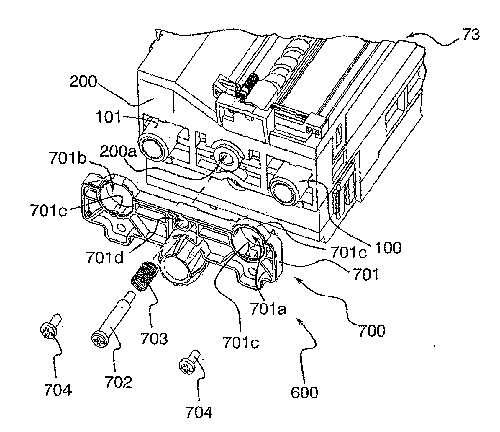
[0082]Moreover, the fixing mechanism 600 of the laser scanning unit 73 based on the present embodiment comprises a biasing mechanism 700 (biasing part) in addition to the configuration at the frame F2 side (the protruding pin 102 and the penetration hole 105), as shown in FIG. 5. Incidentally, the frame F1 is not shown in FIG. 5.

[0083]The biasing mechanism 700 biases and pulls in the housing 200 of the laser scanning unit 73 towards the f...


PUM


Abstract

A fixing mechanism of an optical scanning device, the optical scanning device emitting a light beam and performing a scanning, the optical scanning device further being fixed to a frame at an external part, the optical scanning device further including a housing, and the fixing mechanism including: a penetration hole provided in the frame; and a protruding pin provided at both ends of the housing thereby forming a plurality of protruding pins, wherein at least one of the plurality of protruding pins is insertable to the penetration hole formed in the frame; and a biasing member biasing the housing in a direction.

Description

[0001]The present application claims priority on Japanese Patent Application No. 2010-078006, filed Mar. 30, 2010, the content of which is incorporated herein by reference.BACKGROUND OF THE INVENTION[0002]1. Field of the Invention[0003]The present invention relates to a fixing mechanism of an optical scanning device and an imaging forming apparatus.[0004]2. Description of the Related Art[0005]Conventionally, an optical scanning device, which has been one of the primary components of an image forming unit equipped in an image forming device such as a copier and a complex machine, comprises a housing such that a light beam is guided in an interior. This housing is supported by being fixed to a frame provided within a chassis of an image forming apparatus.[0006]According to an example of a fixing mechanism of an optical scanning device which has been suggested, a housing of the optical scanning device is screw-fastened using a standard pin such that a screw part is provided on a frame....

Claims


Application Information

Patent Timeline
Patent Type & Authority Applications(United States)
IPC IPC(8): B41J2/44H05K7/14
CPCG03G15/04072G03G21/1642G03G2221/1654G03G2215/0404G03G2221/1636G03G21/1666
Inventor TAKAHASHI, HIROKIOHNISHI, MASATOUCHIDA, KOUSUKE
Owner KYOCERA DOCUMENT SOLUTIONS INC
Why Eureka
Try Eureka