Electronic apparatus and disk drive suspension

a technology of electronic equipment and disk drive, which is applied in the field of electronic equipment, can solve the problems of poor adhesion to the conductive resin, inability to reduce the electrical resistance between the conductive resin and the conductive plate member, and inability to reduce the electrical resistance between the conductive resin and the conductive plate member, and achieve the effect of reliable electrical conduction

Active Publication Date: 2011-10-06
NHK SPRING CO LTD
View PDF11 Cites 75 Cited by
  • Summary
  • Abstract
  • Description
  • Claims
  • Application Information

AI Technical Summary

Benefits of technology

[0012]This invention provides an electronic apparatus, in which an electrical component, such as a microactuator element, and an electrically conductive plate member are

Problems solved by technology

In some cases, however, electrical resistance between the conductive resin and conductive plate member cannot be reduced by simply applying and curing the conductive resin.
When a continuity test is conducted in a hot humid atmosphere, in particular, the electrical resistance be

Method used


Image

  • Electronic apparatus and disk drive suspension
  • Electronic apparatus and disk drive suspension
  • Electronic apparatus and disk drive suspension

Examples


first embodiment

[0027]A disk drive suspension according to the present invention will now be described with reference to FIGS. 1 to 6.

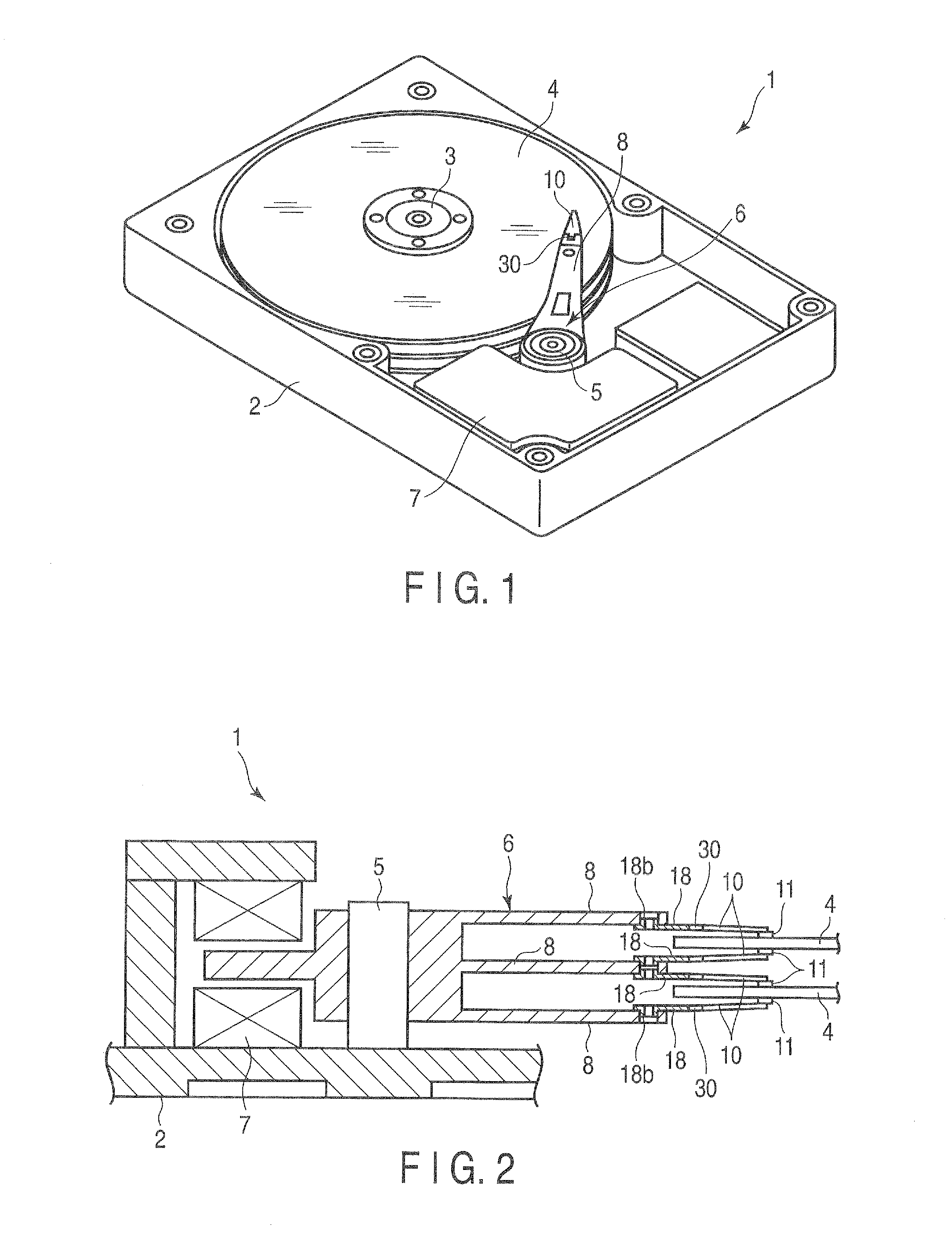
[0028]A disk drive (HDD) 1 shown in FIG. 1 comprises a case 2, spindle 3, disks 4 rotatable about the spindle 3, carriage 6 turnable about a pivot 5, positioning motor (voice coil motor) 7 for actuating the carriage 6, etc. The case 2 is covered by a lid (not shown).

[0029]FIG. 2 is a sectional view typically showing a part of the disk drive 1. As shown in FIG. 2, the carriage 6 comprises arms (carriage arms) 8. A suspension 10 is mounted on the distal end portion of each arm 8. A slider 11, which constitutes a magnetic head, is disposed on the distal end portion of the suspension 10. When each disk 4 is rotated at high speed, an air bearing is formed between the disk 4 and the slider 11.

[0030]If the carriage 6 is turned by the positioning motor 7, the suspension 10 moves radially relative to the disk 4. Thereupon, the slider 11 moves to a desired track of the disk 4....

second embodiment

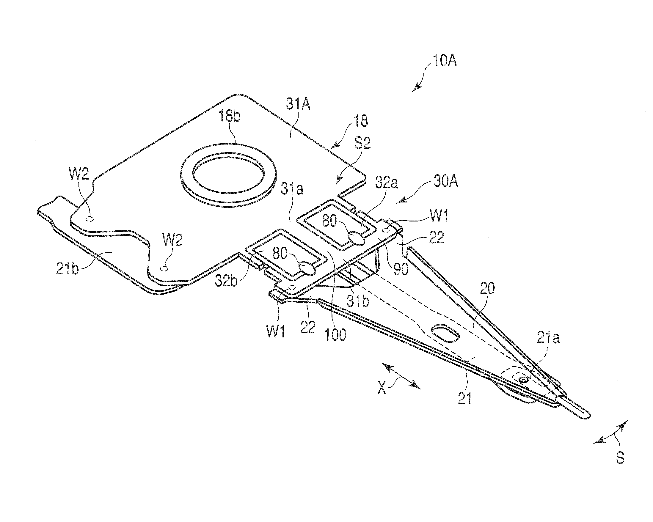
[0062]FIG. 7 shows a suspension 10A with a microactuator mounting section 30A according to a The mounting section 30A comprises a pair of microactuator elements 32a and 32b. An extended portion 100 is formed on a conductive plate member 31A that also serves as a baseplate. A movable part 31b is disposed on the distal end of the extended portion 100. The microactuator elements 32a and 32b are arranged parallel to each other between a stationary part 31a and the movable part 31b of the conductive plate member 31A.

[0063]In this suspension 10A, a boss portion 18b is formed by pressing the conductive plate member 31A that doubles as the baseplate. The boss portion 18b is secured to its corresponding arm 8 of the carriage 6 of the disk drive 1 (FIGS. 1 and 2). A thin porous gold plating layer 90 is formed on the entire outer surface of the conductive plate member 31A. The outer surface of the conductive plate member 31A includes region S2 in which the conductive resin members 80 are arra...


PUM


Abstract

A microactuator element as an example of an electrical component is disposed on a metallic, electrically conductive plate member. A conductive resin member is disposed on a current-carrying part of the conductive plate member and a conduction part of the microactuator element. A thin porous plating layer of thickness 100 nm or less includes a large number of gold particles is formed in a region of a surface of the conductive plate member which covers the current-carrying part. The conductive resin member is secured to the conductive plate member through the thin porous gold plating layer and electrically connected to the conductive plate member.

Description

CROSS-REFERENCE TO RELATED APPLICATIONS[0001]This application is based upon and claims the benefit of priority from prior Japanese Patent Application No. 2010-083945, filed Mar. 31, 2010, the entire contents of which are incorporated herein by reference.BACKGROUND OF THE INVENTION[0002]1. Field of the Invention[0003]This invention relates to an electronic apparatus, such as a disk drive suspension, comprising an electrical component, such as a microactuator.[0004]2. Description of the Related Art[0005]A hard disk drive (HDD) is used in an information processing apparatus, such as a personal computer. The HDD comprises a magnetic disk rotatable about a spindle, a carriage turnable about a pivot, etc. The carriage, which comprises an actuator arm, is configured to be turned transversely relative to tracks about the pivot by a positioning motor, such as a voice coil motor.[0006]A suspension is mounted on the actuator arm. The suspension comprises a load beam and flexure superposed ther...

Claims


Application Information

Patent Timeline
IPC IPC(8): G11B21/24
CPCG11B5/4873G11B5/4806
Inventor FUCHINO, HIDEKI
Owner NHK SPRING CO LTD
Why Eureka
Try Eureka