
Cochlear implant stabilization and positioning device

a cochlear implant and positioning technology, applied in the field of cochlear implant hearing aid devices, can solve the problems of affecting the efficiency of electrical signal transfer between the electrode and the nerve to be stimulated, the cochleostomy site not sealing well, and the outcome of unwanted electrode movement, so as to reduce the diameter of the interior passageway and improve the stabilization

Inactive Publication Date: 2011-10-06
DOMESTIC ASSET LLP
View PDF2 Cites 23 Cited by
  • Summary
  • Abstract
  • Description
  • Claims
  • Application Information

AI Technical Summary

Benefits of technology

[0021]In another embodiment, the stabilizer includes a body member, wherein the body member includes an outer surface and an interior passageway, with the outer surface comprising the tissue engaging portion of the stabilizer, and the interior passageway comprising a coupler portion of the stabilizer. The body member is preferably comprised of a compressible material for permitting the user to compress the body member to reduce the outer surface of the body member prior to the insertion of the body member into a cochlea opening, re-expand the outer surface upon release of the body member after insertion into the opening, and to reduce the diameter of the interior passageway to better secure an electrode portion of a receiver stimulator passing through the interior passageway.
[0022]One feature of the present invention is that although it has particular utility when used in connection with hearing aid-type devices, the device is also flexible enough in its potential uses to have utility in connection with other medical applications wherein the need for better stabilization in the area around a surgically implanted electrode is desirable.

Problems solved by technology

This imprecision leads to variations in outcome and unwanted electrode movement.
An insecure, or imprecise electrode array placement can cause electrode arrays to move away from their intended positions, and cause cochleostomy sites to not seal well.
Therefore, the movement of the electrode away from its most desirable position adversely impacts the efficiency of the electrical signal transfer between the electrode and the nerve to be stimulated.
Unfortunately, the receiver stimulator cannot be secured within the pocket with traditional suture “ties” because it is not reachable when it is placed in the final position in the deepest recess of the pocket.
Most notably, the body portion receiver-stimulator may migrate to a first position low over the ear and interfere with the positioning and retention of the Speech Processor on the ear.
The two components (Speech Processor and the body portion of the receiver-stimulator) may also knock against each other causing clicking sounds and disruption of electrical signals.
These clicking sounds and electrical signal disruptions can be rather annoying to a patient.
The external ear may also be bent in a downward position causing discomfort to the patient.

Method used


Image

  • Cochlear implant stabilization and positioning device
  • Cochlear implant stabilization and positioning device
  • Cochlear implant stabilization and positioning device

Examples


first embodiment

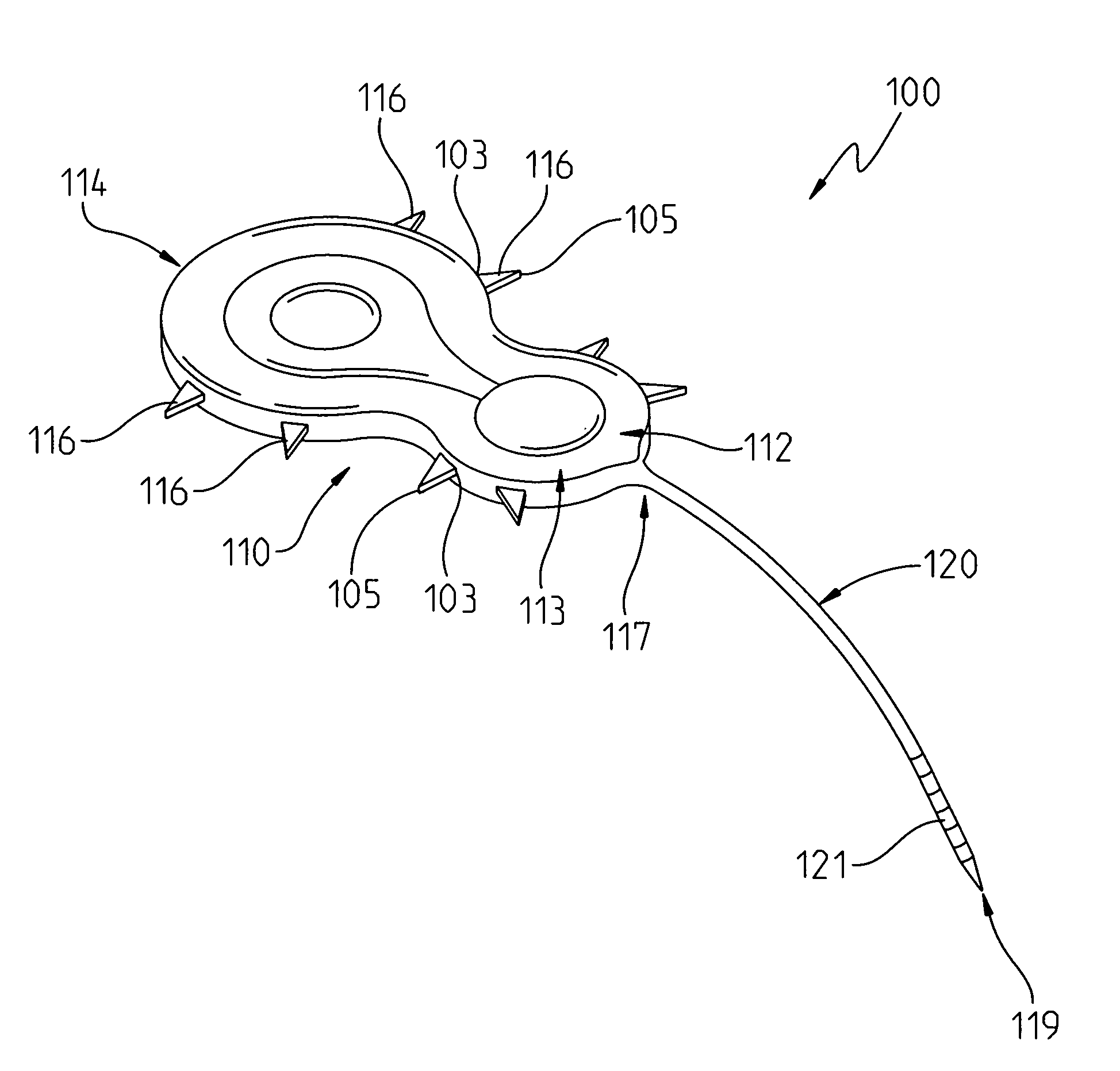
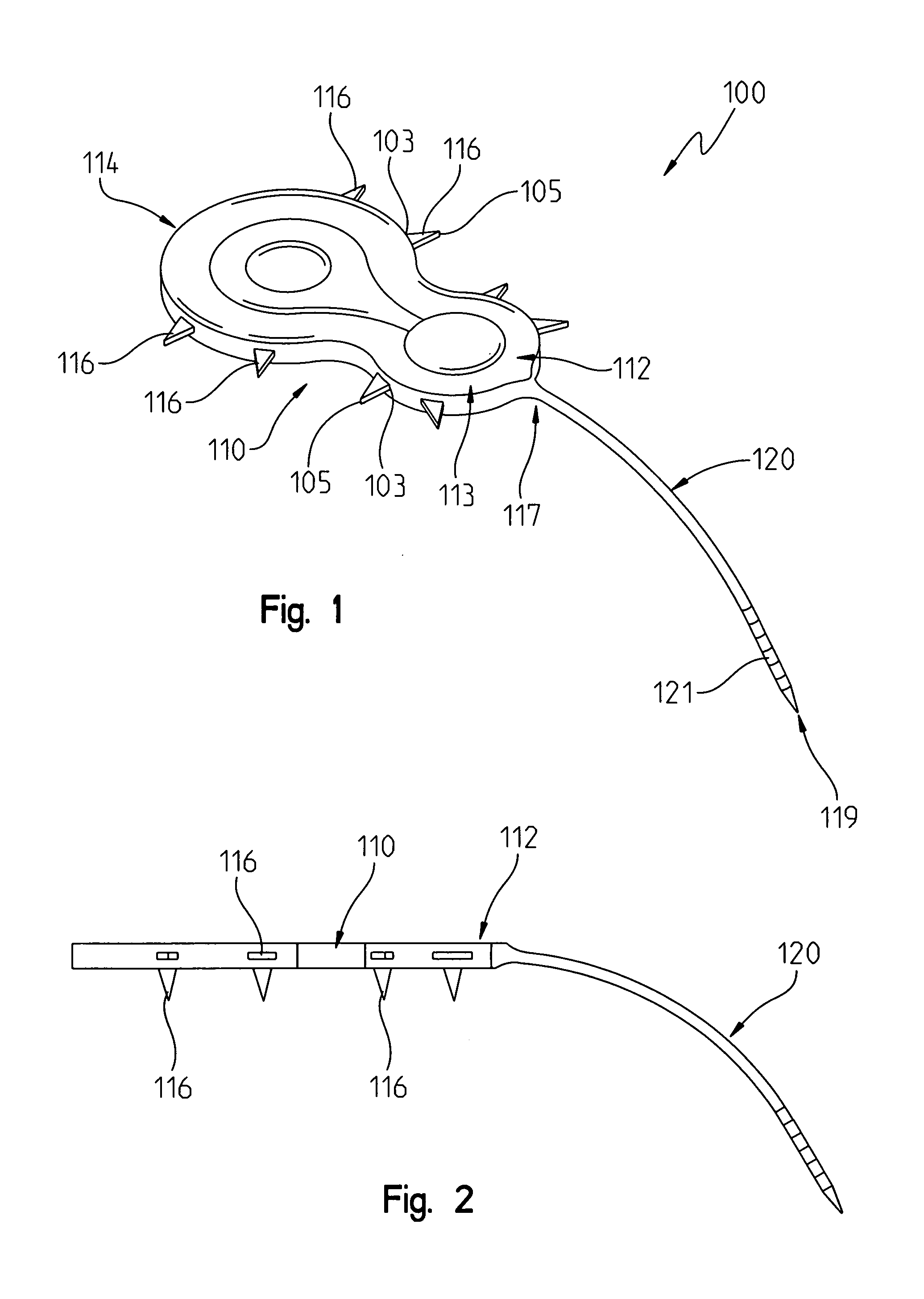
[0047]The first embodiment implant system 100 is shown in FIGS. 1 and 2 as comprising a cochlear implant receiver-stimulator 100. The receiver stimulator 100 includes a body portion 112. The body portion 112 that includes a casing 113 for internally containing the electronic circuitry necessary for the device 100 to operate. The receiver stimulator 110 also includes a stimulation delivery electrode array 120 that is long and thin and has an appearance similar to a tail. The electrode array includes a proximal end 117 attached to the body portion and a distal end portion 119 that is sized and configured for insertion through a cochleostomy opening into the interior of a cochlea.

[0048]A plurality of signal transmitting studs 121 are disposed at the distal end portion 119 for transmitting electrical segments to closely positioned neural receptors for the Organ of Corti. Examples of such stimulation delivery electrode arrays can be found in the Applicants' above referenced patents and a...

second embodiment

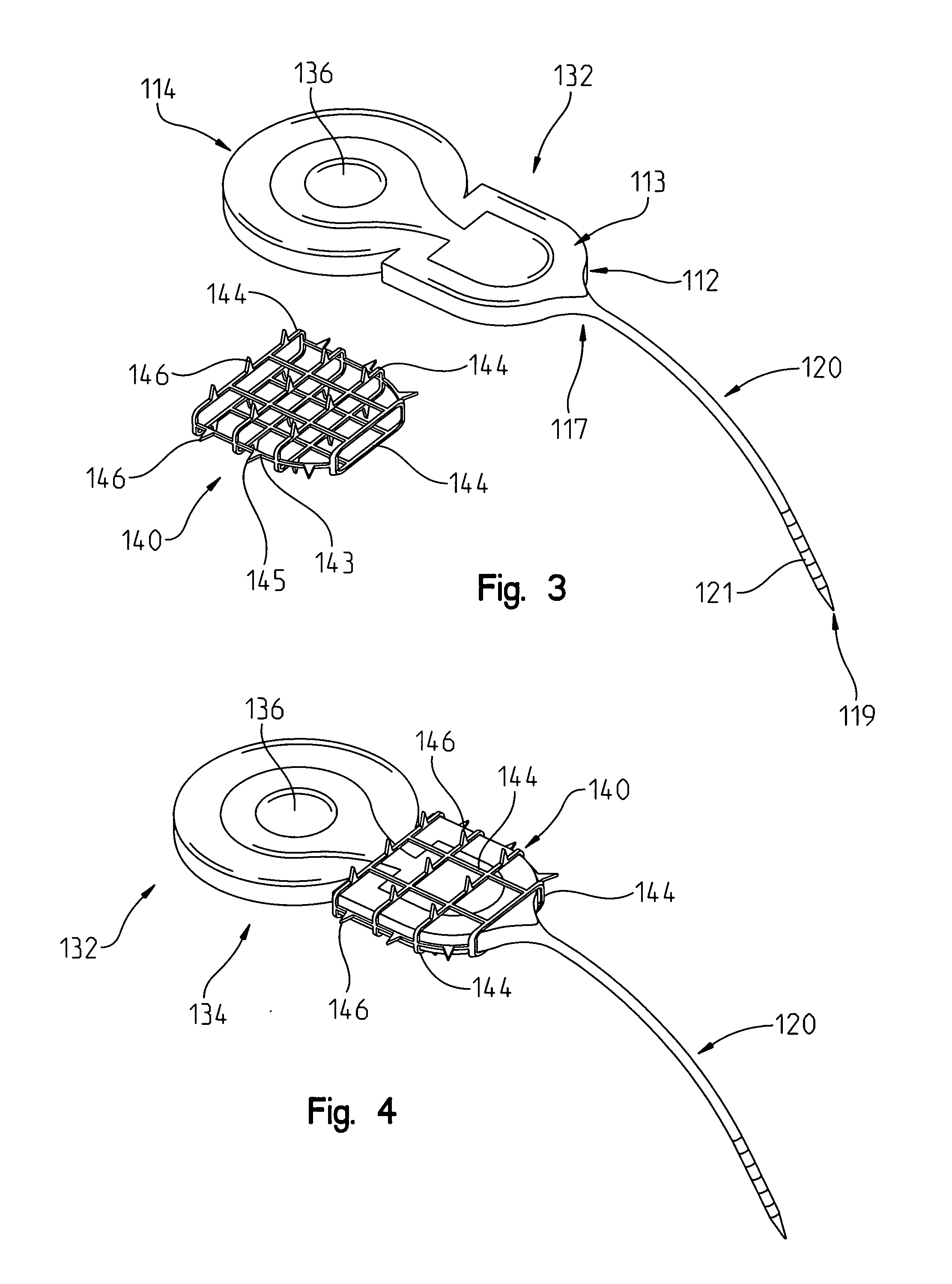
[0050]the stimulator-receiver 132 body 112 position maintaining device includes a cage-like wrap-around 140 having a hollow interior 141 for receiving the body 112 of implant 121. The cage 140 may be a separate device from the cochlear implant body 112 (FIGS. 3 and 4). The cage 140 may be provided to be separate from body 112, or cage 140 may be coupled to the body 112 of implant receiver-stimulator 132 at the factory and come packaged as an assembled, one piece unit (FIG. 4). The cage 140 may be constructed from any of metal, plastic, composite, or an absorbable material.

[0051]Turning now to FIGS. 3 and 4, the assembly 121 includes a cochlear implant receiver-stimulator 132 that includes a body portion 112, including a casing 113 and a side edge 114, and an array of stimulation delivery electrodes 120. A signal providing electrode 120 is provided for delivering a signal to the cochlear implant receiver-stimulator 132 from the signal generating sources such as the speech processor (...


PUM


Abstract

A stabilizer is disclosed for use with a cochlear implant receiver stimulator having a body portion and an electrode portion implanted subcutaneously adjacent to a body tissue. The stabilizer is provided for stabilizing the position of the implant receiver relative to the body tissue. The stabilizer has a tissue engaging portion for grippingly engaging the body tissue to fixedly position the stabilizer with respect to the body tissue. The stabilizer also includes a coupler portion for fixedly positioning the stabilizer with respect to the receiver stimulator. The tissue engaging portion and coupler portion cooperatively interact with the receiver stimulator and the body tissue to fix the relative position of the body tissue and receiver stimulator.

Description

I. REFERENCE TO RELATED PATENT APPLICATIONS[0001]This U.S. non-provisional patent application claims the benefit of and / or priority to Fritsch et al., U.S. provisional patent applications, Ser. No. 61 / 341,329 filed Mar. 30, 2010 entitled “Cochlear Implant Electrode Stabilizer Device”; Ser. No. 61 / 341,335 filed Mar. 30, 2010 entitled “Cochlear Implant Electrode Bracket Device”; and 61 / 341,380 filed Mar. 30, 2010 entitled “Cochlear Implant Pocket Retainer Device”; and Ser. No. 61 / 341,469 filed 30 Mar. 2010, entitled “Cork for Cochlear Implant”, the entire contents of which are all specifically incorporated herein by reference.II. TECHNICAL FIELD OF THE INVENTION[0002]The present invention relates to cochlear implant hearing-aid devices, and more particularly, to a positioning stabilization device that is used to retain and secure a cochlear implant device and electrode at the desired position on the patent within a surgically created tissue pocket.III. BACKGROUND OF INVENTION[0003]A c...

Claims


Application Information

Patent Timeline
Patent Type & Authority Applications(United States)
IPC IPC(8): A61F11/04
CPCA61N1/0541A61N1/375A61N1/36032A61N1/37518A61N1/36038
Inventor FRITSCH, MICHAEL H.FRITSCH, JOHN H.FRITSCH, JOSEPHINE
Owner DOMESTIC ASSET LLP
Learn More