Multi-processor system and lock arbitration method thereof

Inactive Publication Date: 2011-10-06
PANASONIC CORP
View PDF10 Cites 16 Cited by
  • Summary
  • Abstract
  • Description
  • Claims
  • Application Information

AI Technical Summary

Benefits of technology

[0008]In recent years, with improvement of performance of electronic devices, emphasis has been put on the fact that specified functions are implemented in real time. For example, the auto-focusing functions of digital cameras are required t

Problems solved by technology

Because of this, there may be a chance that processing assigned with a higher priority continues to be pla

Method used


Image

  • Multi-processor system and lock arbitration method thereof
  • Multi-processor system and lock arbitration method thereof
  • Multi-processor system and lock arbitration method thereof

Examples


Example

Embodiment 1

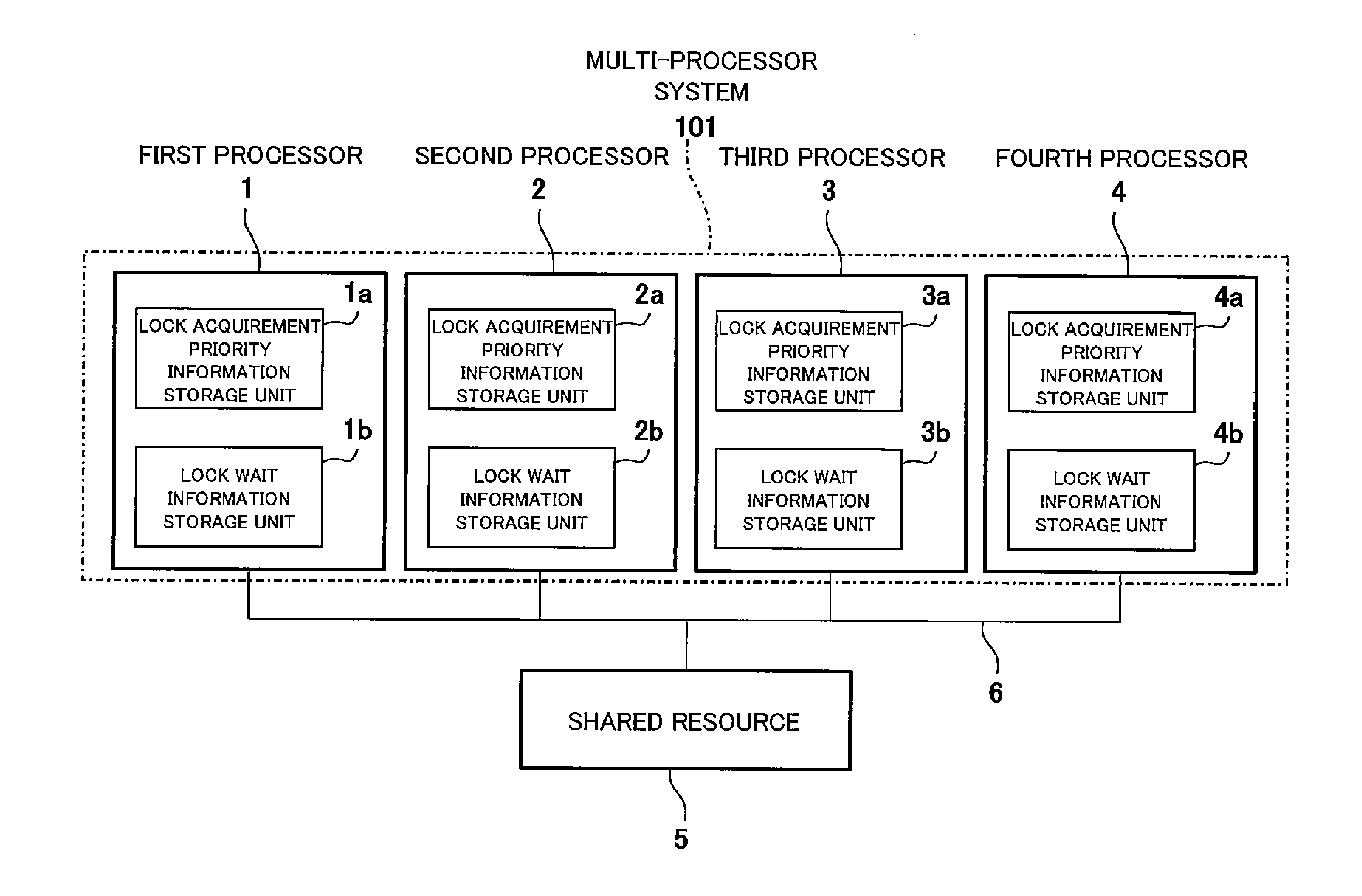
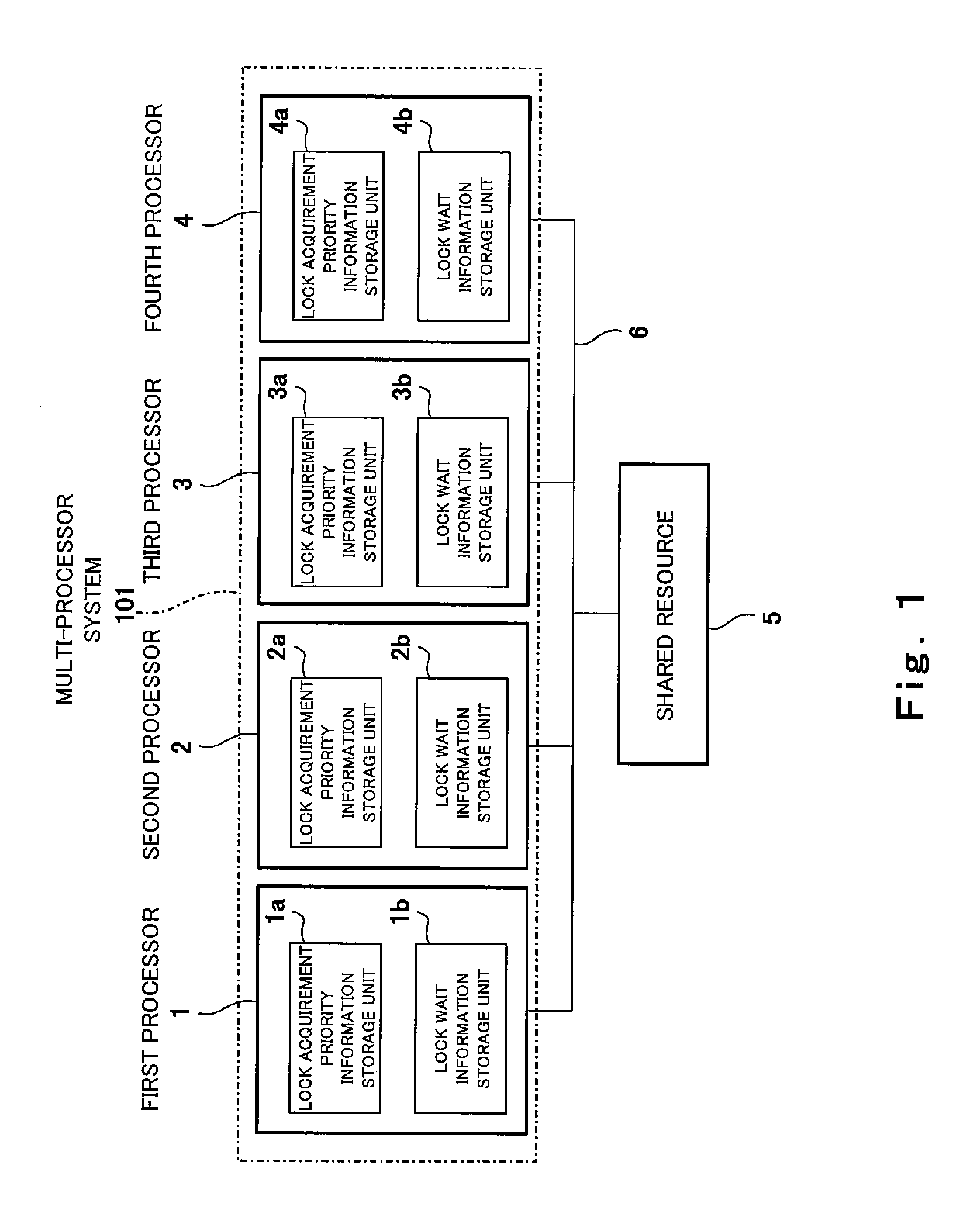
[0039]FIG. 1 is a circuit diagram showing a configuration of a multi-processor system according to Embodiment 1 of the present invention.

[0040]As shown FIG. 1, a multi-processor system 101 of Embodiment 1 includes first to fourth processors 1˜4. The first to fourth processors 1˜4 are connected to a shared (common) resource 5 through a bus 6. The first processor 1 includes a lock acquirement priority information storage unit la and a lock wait information storage unit 1b. The second processor 2 includes a lock acquirement priority information storage unit 2a and a lock wait information storage unit 2b. The third processor 3 includes a lock acquirement priority information storage unit 3a and a lock wait information storage unit 3b. The fourth processor 4 includes a lock acquirement priority information storage unit 4a and a lock wait information storage unit 4b.

[0041]The lock acquirement priority information storage units 1a, 2a, 3a, and 4a serve to store lock acquiremen...

Example

Embodiment 2

[0065]FIG. 4 is a circuit diagram showing a configuration of a multi-processor system according to Embodiment 2 of the present invention.

[0066]A multi-processor system 201 of the present embodiment is identical in basic configuration to the multi-processor system 101 of Embodiment 1 but is different from the same in that the lock acquirement priority is changed in the multi-processor system 201 of the present embodiment. Hereinafter, this difference will be in a large part described.

[0067]As shown in FIG. 4, in the multi-processor system 201 of the present embodiment, first to fourth processors 1˜4 include lock acquirement trial number storage units 1c, 2c, 3c, and 4c, respectively. The lock acquirement trial number storage units 1c, 2c, 3c, and 4c serve to store the number of times trial is made to acquire a lock, and are constituted by circuit elements capable of storing data. In the present embodiment, the lock acquirement trial number storage units 1c, 2c, 3c, and 4c...

Example

MODIFIED EXAMPLE 1

[0079]In Modified Example 1, the processors 1˜4 are respectively configured to change the lock acquirement priority information according to the priority of a task being executed or interrupt processing, instead of the number of times trial is made to acquire a lock.

[0080]To be specific, the processors 1˜4 update the lock acquirement priority information in task dispatch processing or interrupt entrance / exit processing. For example, when the first processor 1 performs dispatch from a task A to a task B, it changes the lock acquirement priority information from the priority of the task A to the priority of the task B. When an interrupt request for interrupt processing C is issued in a state where the task B is being executed and the task B shifts to the interrupt processing C, the first processor 1 changes the lock acquirement priority information to the priority of the interrupt processing C. In accordance with this configuration, the lock acquirement priority inf...


PUM


Abstract

A multi-processor system of the present invention comprises a plurality of processors each configured to lock a shared resource and process a task; each of the processors including a lock wait information storage unit for storing lock wait information indicating whether or not the processor is waiting for acquirement of a lock of the shared resource; and a lock acquirement priority information storage unit for storing lock acquirement priority information indicating a priority according to which the shared resource is acquired; and each of the processors being configured to acquire the lock of the shared resource based on the lock wait information and the lock acquirement priority information.

Description

[0001]This is a continuation application under 35 U.S.C. 111(a) of pending prior International application No. PCT / JP2009 / 005101, filed on Oct. 2, 2009. The disclosure of Japanese Patent Application No. 2008-316460 filed on Dec. 12, 2008 including specification, drawings and claims is incorporated here in by reference in its entirety.BACKGROUND OF THE INVENTION[0002]1. Field of the Invention[0003]The present invention relates to a multi-processor system. Particularly, the present invention relates to a system in which a plurality of processors require a lock of a resource, and a lock arbitration method thereof[0004]2. Description of the Related Art[0005]In a lock arbitration method of a conventional multi-processor system, a resource flag indicating whether or not a lock is being executed is used. The resource flag is ON (‘1’) when there exists a processor which is executing a lock in the system and is OFF (‘0’) when there does not. Each processor checks the resource flag without fa...

Claims


Application Information

Patent Timeline
IPC IPC(8): G06F13/00
CPCG06F9/526
Inventor ICHINOSE, NAOYA
Owner PANASONIC CORP
Why Eureka
Try Eureka