Shielded cable

a shielding cable and shielding technology, applied in the direction of insulated conductors, power cables, cables, etc., can solve the problems of loss of signal strength, drop in signal level, and insufficient strength of shielding conductors, so as to eliminate precipitous signal attenuation

Inactive Publication Date: 2011-10-13
SUMITOMO ELECTRIC IND LTD
View PDF22 Cites 49 Cited by
  • Summary
  • Abstract
  • Description
  • Claims
  • Application Information

AI Technical Summary

Benefits of technology

[0011]In accordance with the shielded tape of the present invention, it is possible to eliminate precipitous signal attenuation in high-frequency ranges.

Problems solved by technology

In this shielded cable, the shield conductor does not have sufficient strength and tends to be cut if only metal foil (e.g., aluminum foil) is used, so metal coated resin tape in which resin tape is clad with metal foil is commonly used.
However, with shielded cables having such a configuration, suck-out (precipitous loss of signal strength) arises at high frequencies of 3 GHz or greater, and there have been problems with drops in the signal level.

Method used


Image

  • Shielded cable
  • Shielded cable
  • Shielded cable

Examples


Embodiment Construction

[0017]The above-mentioned features and other features, aspects, and advantages of the present invention will be better understood through the following description, appended claims, and accompanying drawings. In the explanation of the drawings, an identical mark is applied to identical elements and overlapping explanations are omitted for the sake of brevity.

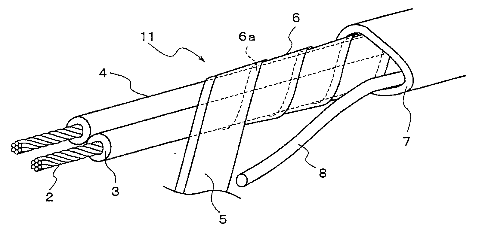
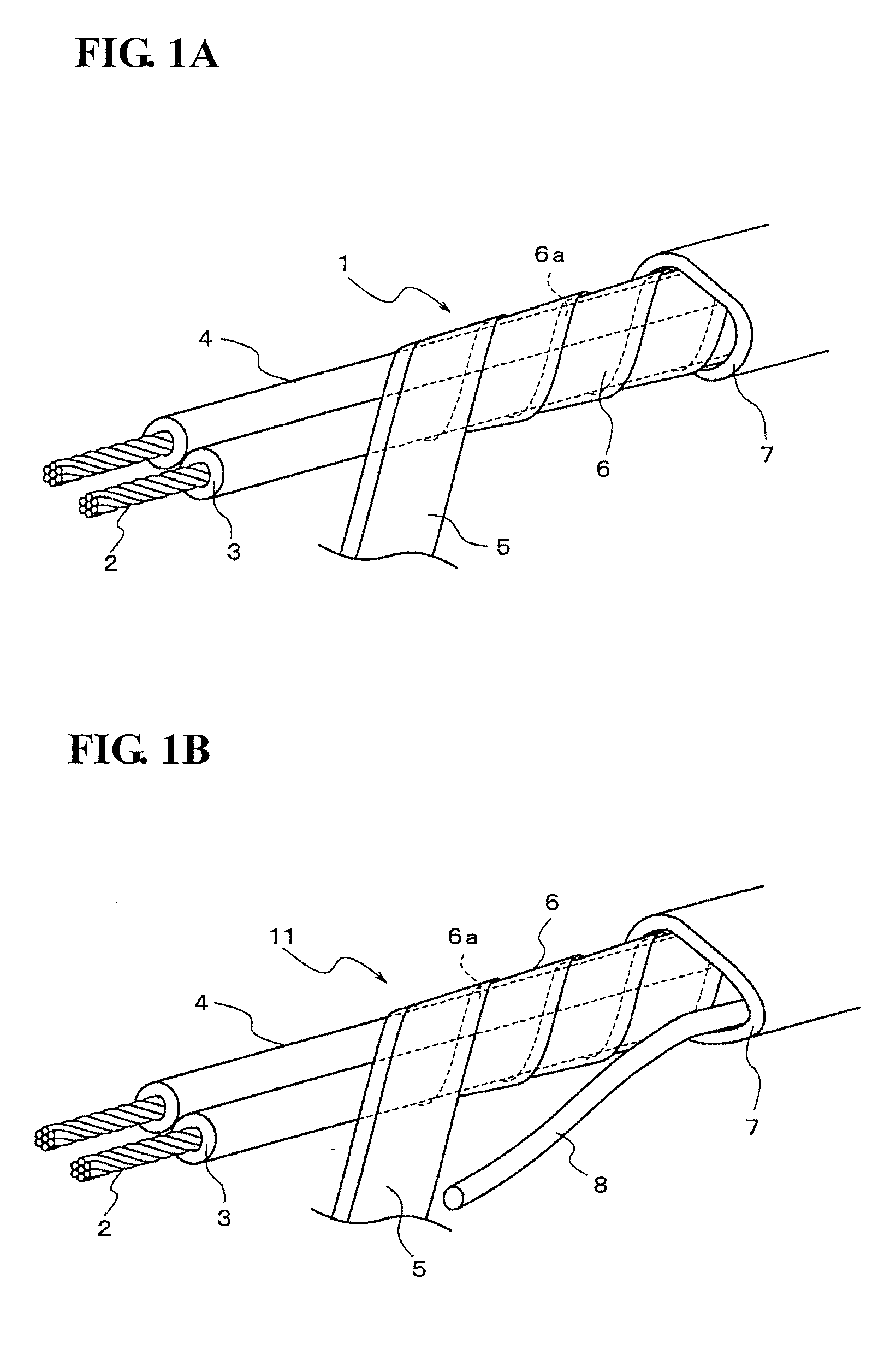
[0018]FIG. 1A is an oblique view showing the shielded cable 1 in an embodiment of the present invention. The shielded cable 1 includes two signal wires (or core wires) 4 in which a signal conductor 2 composed of a single core wire or a twisted wire is covered with an insulator 3. The two signal wires 4 can be aligned parallel to each other or can have a twisted paired cable configuration.

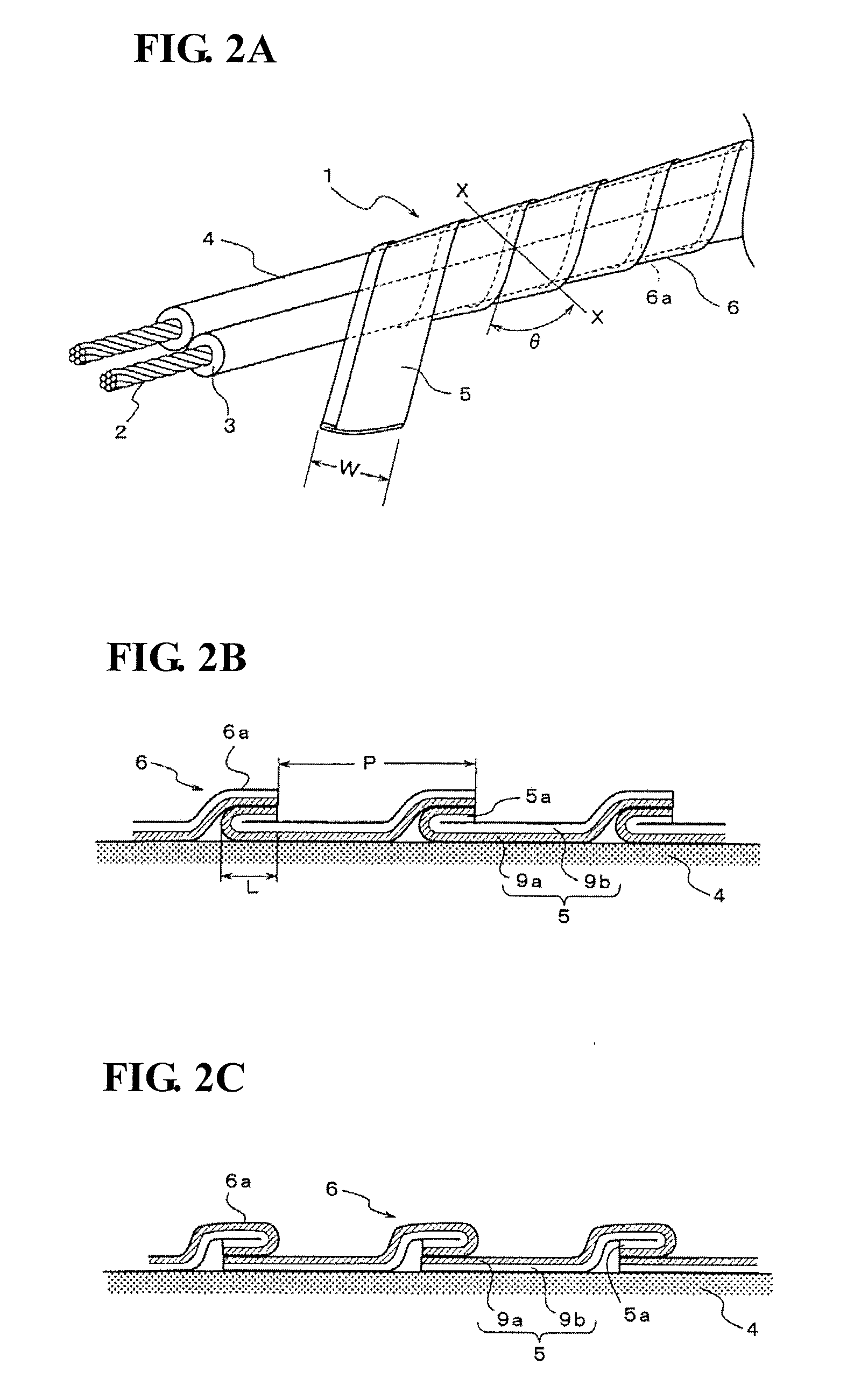
[0019]A metal coated resin tape 5 as a shield conductor 6 is helically wound around the outer circumference of a pair of two signal wires 4, and both of the two signal wires 4 are shielded. The metal coated resin tape 5, as described below, is w...


PUM

PropertyMeasurementUnit
frequenciesaaaaaaaaaa
outer diameteraaaaaaaaaa

Abstract

There is provided a shielded cable wherein a metal coated resin tape is helically wound, whereby a plurality of signal cables are shielded, and no sudden signal attenuation occurs in high frequency ranges. A shielded cable has a shield conductor produced by helically winding a metal coated resin tape together around the circumference of a plurality of signal wires, upper and lower metal foils are in electrical contact with each other in overlap parts of the winding of the metal coated resin tape. The metal coated resin tape is formed with one edge part folded back so that the metal foil is disposed on an outward side. The overlap width of the winding of the metal coated resin tape is one-quarter to one-half of the tape width.

Description

BACKGROUND OF THE INVENTION[0001]1. Technical Field[0002]The present invention relates to a shielded cable having a metal coated resin tape for a shielding wound in a helix around the circumference of two or more signal wires.[0003]2. Description of the Background Art[0004]Shielded cables having a plurality (e.g., a pair) of signal wires are used in the transmission of digital signals in differential transmission systems. With differential signal transmission systems, signals with phases that have been inverted by 180° are input simultaneously into individual signal wires and transmitted. By detecting the signal differential between them on a receiving end thereof, the signal output can be doubled. In addition, noise incurred along the signal pathway extending from a transmission end to the receiving end is added equally to each of the pair of signal wires, resulting in characteristics whereby the noise is cancelled and eliminated when the differential signals are output on the rece...

Claims


Application Information

Patent Timeline
Patent Type & Authority Applications(United States)
IPC IPC(8): H01B9/02
CPCH01B11/1008H01B11/203H01B11/1091H01B11/1025
Inventor MATSUDA, MOTOIKARUBE, KATSUMIOKANO, SATOSHI
Owner SUMITOMO ELECTRIC IND LTD
Why Eureka
Try Eureka