Armrest And Operator Workplace Having Such An Armrest

a technology for operators and workplaces, applied in the field of operator seats, can solve problems such as pain in the corresponding skin areas, and achieve the effect of increasing the comfort and increasing the precision of machine control

Active Publication Date: 2011-10-13
BOMAG
View PDF6 Cites 10 Cited by
  • Summary
  • Abstract
  • Description
  • Claims
  • Application Information

AI Technical Summary

Benefits of technology

[0005]To achieve this object, it is provided according to the present invention that the machine operator seat has an arm support, which is mounted via a guide device on the base part of the armrest, the guide device being implemented in such a way that the arm support is freely displaceable in relation to the base part in a limited longitudinal displacement range along the longitudinal direction of the armrest. An essential aspect of the present invention is therefore primarily that the arm support is not mounted rigidly on the base part of the armrest, as heretofore typical, but rather a guide device is provided for connecting the arm support to the base part, which allows a mobility of the arm support in relation to the rigid base part. The mobility of the arm support is not unlimited, but rather is allowed by the guide device in a defined and limited longitudinal displacement range. In other words, the arm support is therefore movable along the base part in the longitudinal direction or viewing direction of the operator seated in the machine operator seat. It is provided according to the invention that the arm support, to increase the comfort, is not fixedly fixed solely by corresponding setting options, but rather is freely or non-fixedly displaceable. If the operator seated in the machine operator seat therefore presses the at least one operating element forward, the arm resting on the arm support, specifically the forearm, can follow this movement, in that the arm support is displaced jointly with the arm on the base part forward toward the at least one operating element. This is also true conversely for a reverse movement of the at least one operating element, for example. The arm support can therefore follow the movement of the arm of the operator. In particular the forearm of the operator must therefore no longer slide back-and-forth on the arm support, but rather can complete the operating movements together with the arm of the operator resting on the arm support. It is therefore possible for the operator to support his arm continuously and over the entire operating procedure on the arm support, which results in substantial relief of the operator. In addition, the optimum relative positioning between the arm, the at least one operating element, in particular a driving lever handle or a joystick controller, and the arm support can always be maintained, which finally allows a substantial increase of the precision of the machine control.
[0007]The guide device is preferably implemented as self-positioning in such a way that the arm support automatically moves in the unloaded state into a defined starting position with respect to its positioning in the longitudinal direction of the armrest. This embodiment is distinguished in that the arm support always returns into the same starting position from various displaced positions relative to the base part of the armrest upon relief, for example, by raising the arm when exiting the machine. For the operator, it is therefore ensured that the arm support is always located in the same starting position, for example, when the construction machine is put into operation. Such an embodiment is also particularly safe, since it is ensured that emergency devices, such as an emergency stop button, are easily accessible in a hazardous situation and are not concealed by the displaced arm support on the base part, for example. By simply raising the arm, the arm support springs back into its starting position and the operator seated in the machine operator seat can reliably reach the corresponding emergency device.
[0010]Situations frequently occur in which the operator seated in the machine operator seat turns to the side in relation to the longitudinal direction in the machine operator seat, in particular to be able to better observe the lateral area of the construction machine, for example, during work close to the edge, in particular rolling or milling. If he turns toward the side of the armrest, the arm presses against the arm support away from the seat surface. If he looks in the other direction, the arm on the arm support pulls toward the seat surface. This is also the case, for example, if the operator moves from his seated position to a standing position. In order to also be able to compensate for the lateral movements of the arm resting on the arm support, a further preferred embodiment provides the implementation of the guide device in such a way that the arm support is freely laterally displaceable in a limited lateral displacement range. The guide device therefore allows, in addition to the longitudinal displacement movement oriented in the longitudinal direction, a lateral displacement movement running essentially perpendicularly thereto in the horizontal plane. It is therefore possible to freely move the arm together with the arm support in the area of the limited displacement ranges in the horizontal plane. Furthermore, it is also preferable with respect to the lateral displaceability to provide a self-positioning function in the guide device.
[0013]In order to allow the self-positioning function of the sliding carriage, a spring guide rail, on which a restoring spring is situated, preferably runs between the two tabs. The restoring compression spring is therefore tensioned by compression and exerts a restoring force into its non-compressed position in the compressed state. The spring guide rail is guided through the restoring spring in this embodiment. In this way, it is ensured that the restoring compression spring does not arbitrarily deviate in the event of a compression, but rather is compressed along its longitudinal axis and the restoring force acts along the longitudinal axis of the restoring compression spring.
[0017]If a lateral displaceability of the arm support is provided in addition to the longitudinal displaceability of the arm support, the sliding carriage can have at least one oblong hole for guiding the lateral adjustment movement of the arm support in relation to the base part in a further preferred embodiment, in which a guide element situated on the arm support, for example, a guide pin having a guide bush, engages. An oblong hole guide is therefore obtained as a whole using the oblong hole and the guide element, the longitudinal axis of the oblong hole running laterally or orthogonally to the longitudinal direction of the armrest to obtain the lateral mobility.

Problems solved by technology

In the case of such movements, the driver must either always relieve his arm resting on the arm support, which is strenuous in particular in the case of long-lasting work processes and is perceived as annoying.
Alternatively, the machine controller can slide his arm back-and-forth in relation to the arm support, the friction phenomena which occur also being perceived as extremely annoying and, for example, possibly resulting in soreness of the corresponding skin areas.

Method used


Image

  • Armrest And Operator Workplace Having Such An Armrest
  • Armrest And Operator Workplace Having Such An Armrest
  • Armrest And Operator Workplace Having Such An Armrest

Examples


Embodiment Construction

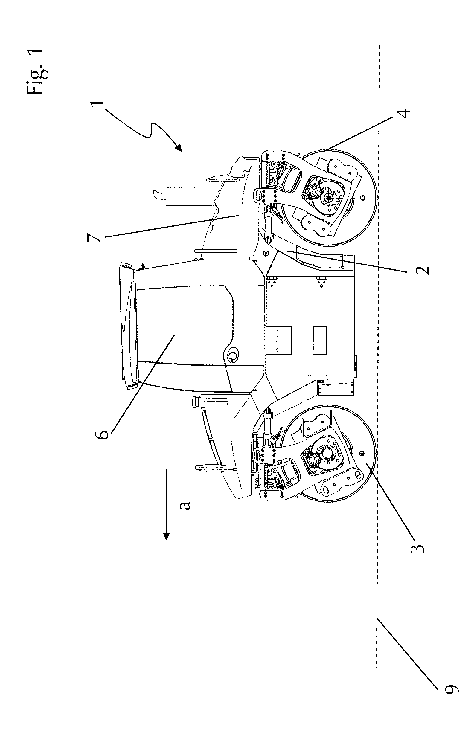
[0037]The side view from FIG. 1 shows a typical construction machine 1, specifically a so-called tandem roller. The essential elements of the construction machine 1 are a machine frame 2, a front roller 3, and a rear roller 4. Furthermore, a drive device 7 is provided, which delivers the drive energy required to drive the construction machine 1. For ground processing, the construction machine 1 is moved in the arrow direction a (forward direction) over the ground 9 to be processed. An operator of the machine is seated in a machine operator seat according to the invention (not visible in FIG. 1) in the cab 6 and controls the machine functions therefrom.

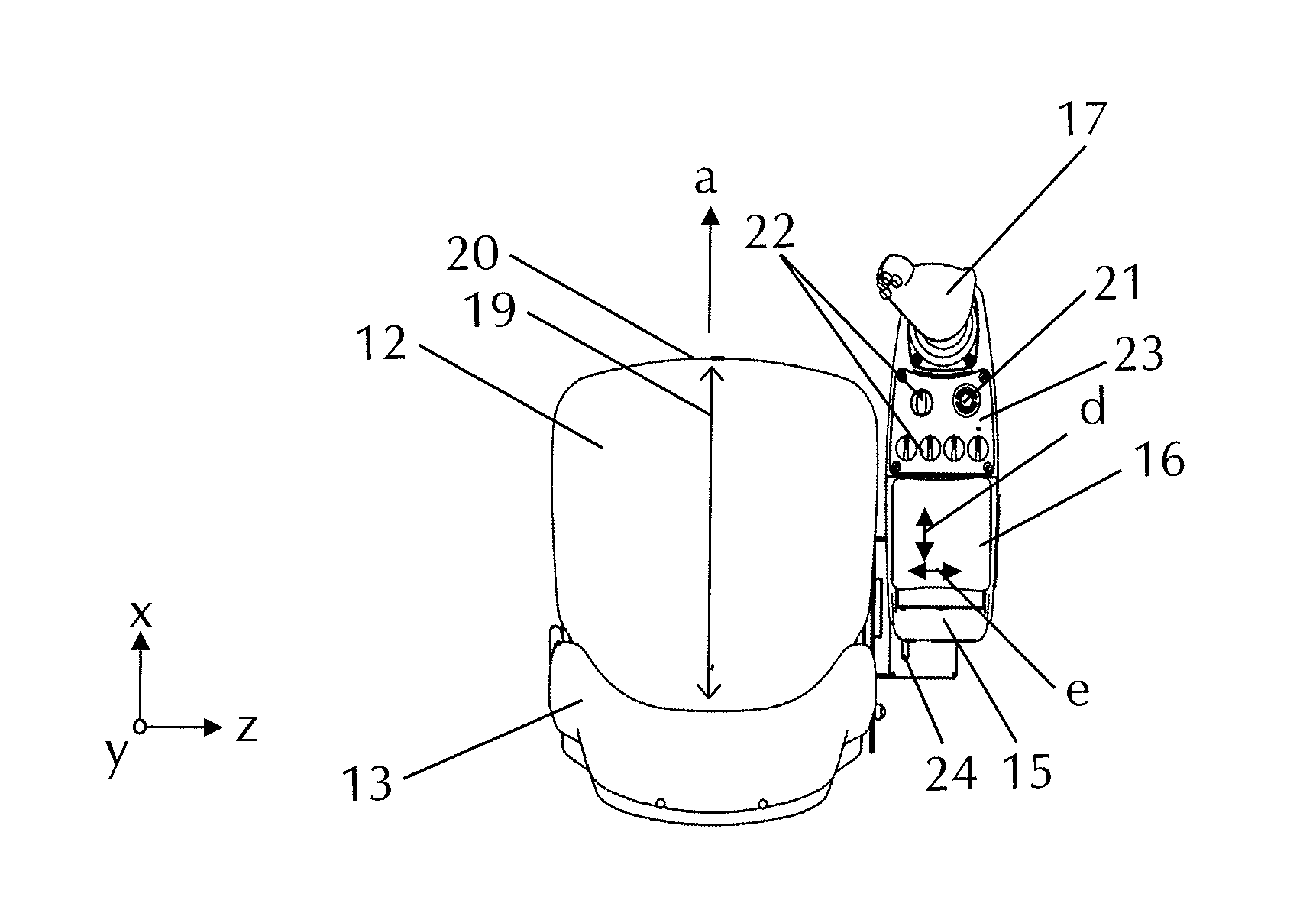
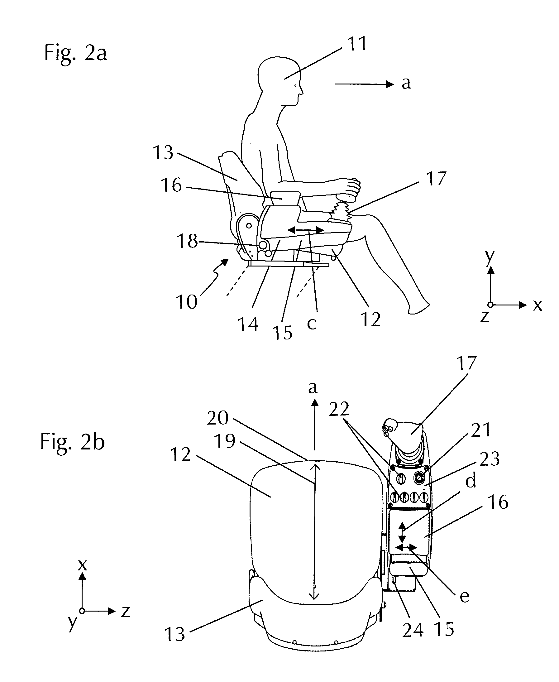
[0038]This machine operator seat 10 is shown in FIG. 2a having an operator 11 seated therein, the machine operator seat 10 not being freely floating, of course, but rather being housed via appropriate connections, which are indicated by dashed lines in FIG. 2a, in the cab 6. The essential elements of the machine operator seat 10 are a ...


PUM


Abstract

The present invention relates to a machine operator seat of a construction machine having a seat surface, a backrest, which is situated opposite to the front seat edge in the longitudinal direction of the seat surface, and at least one armrest situated laterally to the seat surface, comprising a base part, an arm support, and at least one operating element, the arm support being situated in the rear area in the longitudinal direction and the at least one operating element being situated in the front area of the armrest in the longitudinal direction. Furthermore, the present invention relates to a construction machine, in particular a road miller, recycler, stabilizer, or a road roller, in particular a tandem roller, having such a machine operator seat.

Description

FIELD OF THE INVENTION[0001]The invention relates to a machine operator seat having a seat surface, a backrest situated opposite to the seat surface and the front edge of the seat surface in the longitudinal direction, and at least one armrest situated laterally to the seat surface.BACKGROUND OF THE INVENTION[0002]The longitudinal direction of the seat surface is established by the forward-oriented viewing direction of an operator seated in the machine operator seat. The front seat edge is the area of the seat in which the legs are angled. On at least one side of the seat surface, the machine operator seat has an armrest situated laterally to the seat surface, comprising a base part, an arm support, and at least one operating element. The base part thus forms the mount for the arm support and the at least one operating element. The arm support is used so that the machine operator can rest his arm thereon for relief in the seated position. The at least one operating element is, for e...

Claims


Application Information

Patent Timeline
Patent Type & Authority Applications(United States)
IPC IPC(8): B60N2/46B60N2/38B60N2/75
CPCB60N2/4646B60N2/4693B60N2/4653B60N2/773B60N2/777B60N2/797
Inventor HAUBRICH, THOMASKLEIN, THOMAS
Owner BOMAG
Why Eureka
Try Eureka