
Weld-on cast carbon steel roll crusher tooth having silver-brazed tungsten carbide inserts on wear surfaces

a technology of tungsten carbide inserts and roll crusher teeth, which is applied in the direction of grain treatment, manufacturing tools, and so on, can solve the problems of significant damage to the joint integrity, and achieve the effect of minimizing damage to the inserts and softening impacts

Inactive Publication Date: 2011-10-13
KNOTTS BROOK HUGH
View PDF6 Cites 17 Cited by
  • Summary
  • Abstract
  • Description
  • Claims
  • Application Information

AI Technical Summary

Benefits of technology

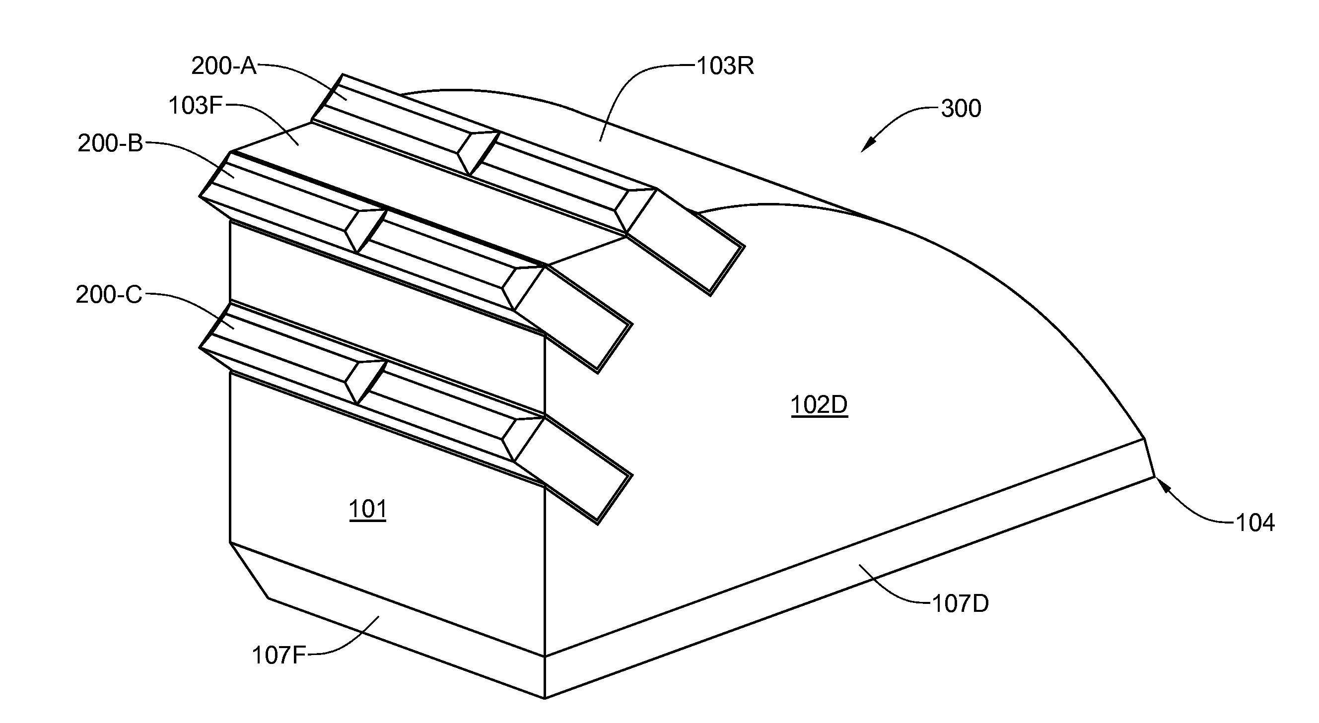
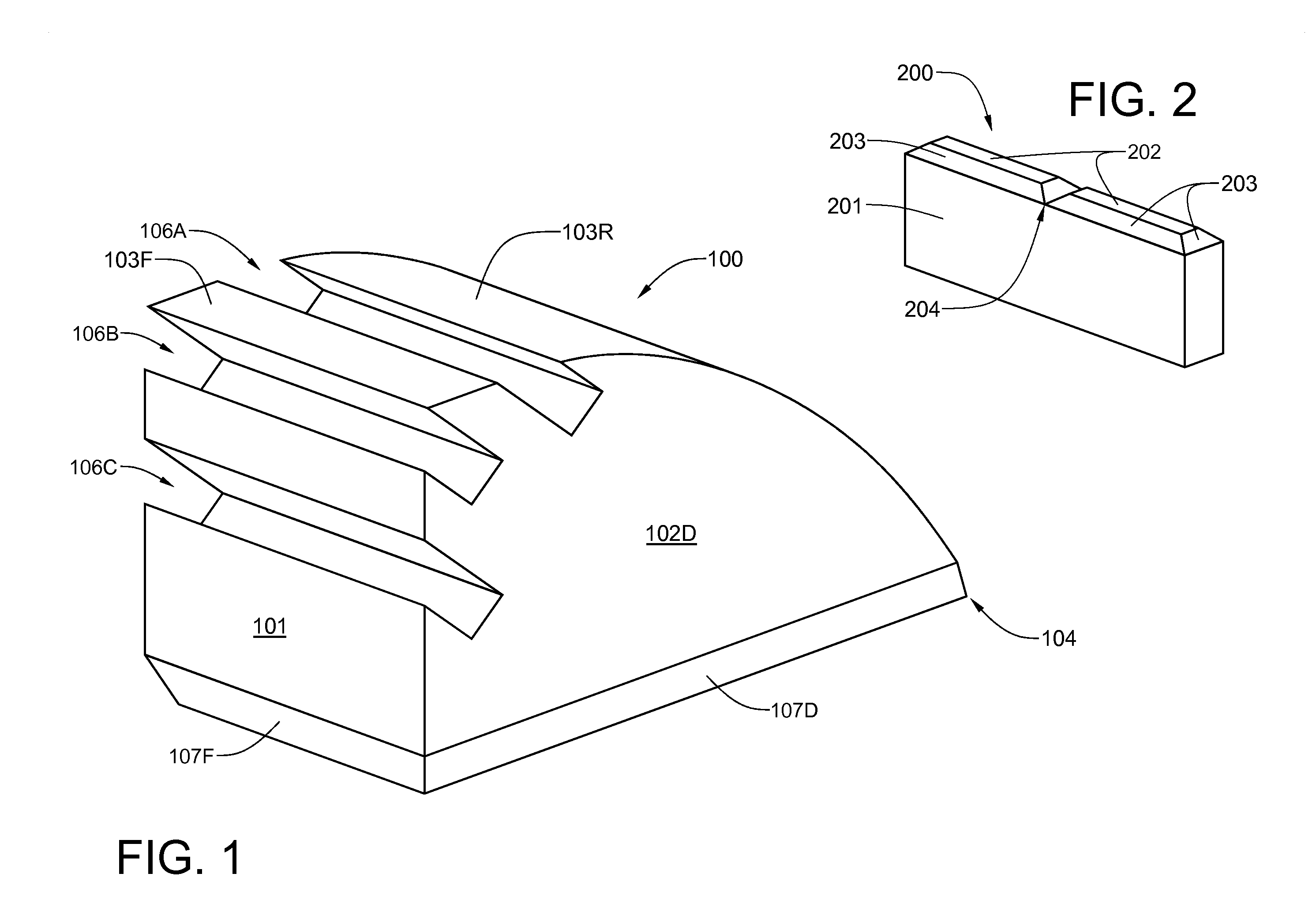
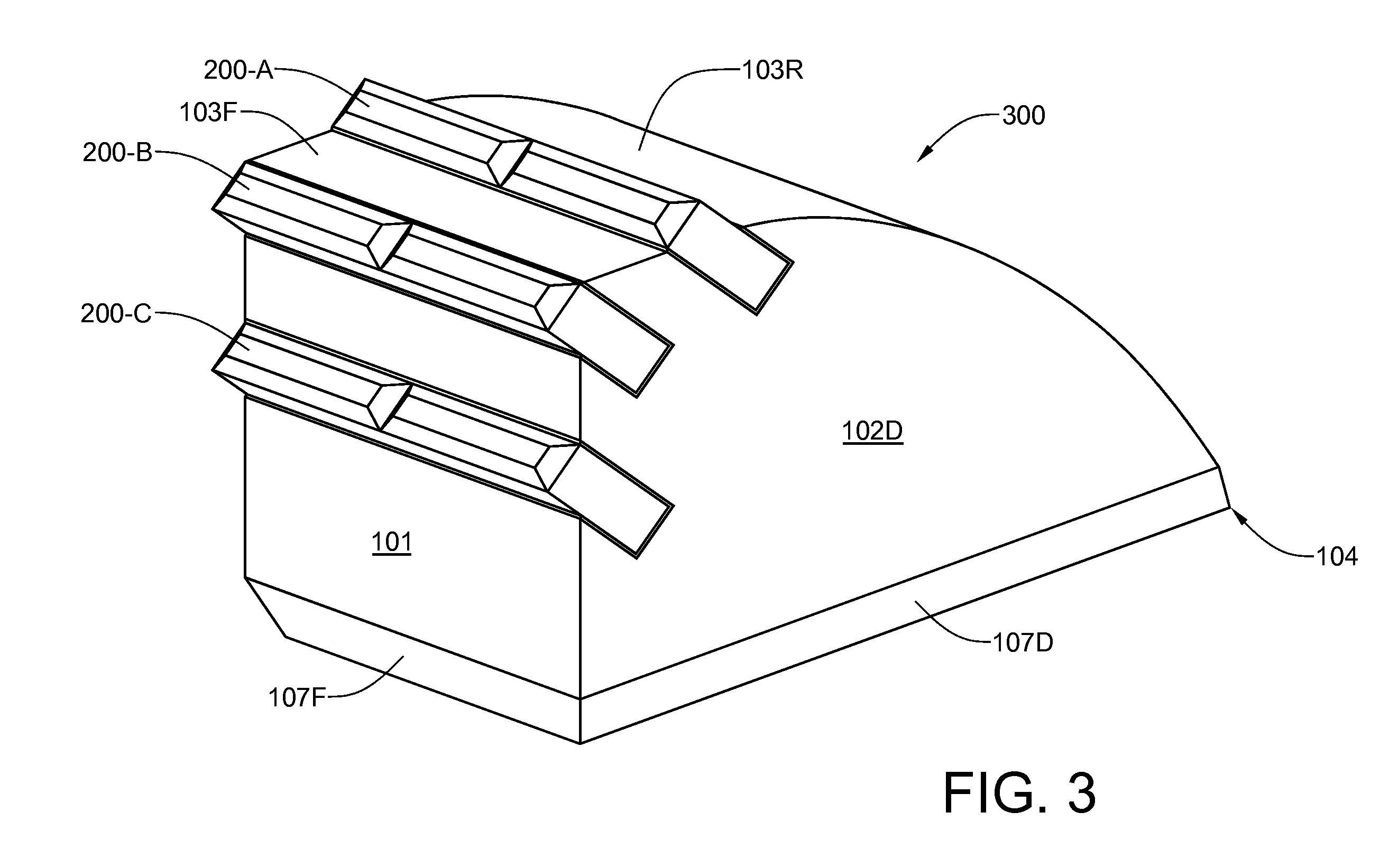
[0018]The present invention provides a durable tooth which can be welded directly to the outer cylindrical surface of the drum of a roll crusher. The tooth includes a cast carbon steel body having multiple transverse grooves for receiving tungsten carbide inserts, which are silver brazed into the grooves. For a preferred embodiment of the tooth, the cast carbon steel body is made of #7018 carbon steel. The silver brazing alloy joins the materials and compensates for the difference in their expansion rates. In addition it provides a cushion between the ultra-hard tungsten carbide inserts and the hard steel body, which softens impacts and minimizes damage to the inserts. The tungsten inserts are located on the surfaces of the tooth that are most susceptible to wear from abrasive action of the coal as the roll crusher operates. The cast carbon steel body 100 can be directly welded to the exterior cylindrical surface of a rotary roll crusher.

Problems solved by technology

In addition, interference fits between components to be joined must be scrupulously avoided, as capillary action will be hindered, and joint integrity will be significantly damaged.

Method used


Image

  • Weld-on cast carbon steel roll crusher tooth having silver-brazed tungsten carbide inserts on wear surfaces
  • Weld-on cast carbon steel roll crusher tooth having silver-brazed tungsten carbide inserts on wear surfaces
  • Weld-on cast carbon steel roll crusher tooth having silver-brazed tungsten carbide inserts on wear surfaces

Examples


Embodiment Construction

[0028]The invention will now be described with reference to the attached drawing FIGS. 1 through 8. It should be understood that although the drawings are intended to be merely illustrative, a reasonable attempt has been made to provide drawings which are close to scale.

[0029]Referring now to FIG. 1, a tooth body 100 is cast from #7018 high-carbon steel. It will be noted that the tooth body 100 has a vertical, generally planar front face 101; a vertical, generally planar right-side face 102D; an upper surface 103 that has a generally planar forward portion 103F and a simple-curved rear portion 103R that begins at the level of the planar forward portion 103F, and transitions so as to make an acute-angled rear edge 104 with a planar lower surface 701 (please refer to the bottom plan view of FIG. 7). The left-side face 102S (please refer to FIG. 5) is a vertical, generally planar surface and a mirror image of the right-side face102D. For a preferred embodiment of the invention, the cas...


PUM

PropertyMeasurementUnit
Angleaaaaaaaaaa
Lengthaaaaaaaaaa
Lengthaaaaaaaaaa

Abstract

A durable, weld-on tooth for roll crushers is provided. The tooth includes a cast high-carbon steel body having multiple transverse grooves for receiving tungsten carbide inserts, which are silver brazed into the grooves. The tungsten inserts are located on the surfaces of the tooth that are most susceptible to wear from abrasive action of the coal as the roll crusher operates. The cast carbon steel body can be directly welded to the exterior cylindrical surface of a rotary roll crusher. For a preferred embodiment of the tooth, the front and side faces of the cast high-carbon steel body have bevels that enable weldments that secure it to the roll crusher drum to be somewhat recessed beneath the cast high-carbon steel body on three sides thereof.

Description

BACKGROUND OF THE INVENTION[0001]1. Field of the Invention[0002]This invention relates to teeth for roll crushers and, more particularly, to teeth which are welded to the outer surface of roll crusher drums.[0003]2. Description of the Prior Art[0004]Roll crushers are compression type crushers widely used extensively in mining operations. There are two basic types of roll crushers. The first employs a single roll operating adjacent a curved stationary anvil plate. The second employs two counter-rotating rolls having parallel axes and a gap between the rolls. Particle output size is determined, in the case of a single roll crusher, by the gap between the roll and the anvil plate or, in the case of a double-roll crusher, by the gap between the rolls. During the operation of a roll crusher, large particles are drawn into the gap by the rotating motion of the roll or rolls and a friction, or nip, angle formed between either the single roll and its adjacent anvil plate or between the two ...

Claims


Application Information

Patent Timeline
IPC IPC(8): E21C35/183
CPCB02C4/08B02C4/305B23K1/0008B23K31/02B23K2203/18B23K35/00B23K2201/20B23K2203/06B23K31/025B23K2101/20B23K2103/06B23K2103/18B23K2103/52
Inventor KNOTTS, BROOK HUGH
Owner KNOTTS BROOK HUGH
Learn More