Unlock instant, AI-driven research and patent intelligence for your innovation.

Method for controlling ion energy in radio frequency plasmas

a radio frequency plasma and ion energy technology, applied in the field of surface modification and materials, can solve the problem of not allowing such independent control of these two plasma treatment parameters, and achieve the effect of expanding the sheath region

Inactive Publication Date: 2011-10-13
RUHR UNIV BOCHUM
View PDF7 Cites 46 Cited by
  • Summary
  • Abstract
  • Description
  • Claims
  • Application Information

AI Technical Summary

Benefits of technology

[0010]The present invention provides a method of establishing a DC bias in front of at least one electrode in a plasma operating apparatus by applying a RF voltage as is described in independent claim 1. Embodiments are described in dependent claims 2 through 27. As a note, to conduct a RF current through the plasma, it is obvious that two or more electrodes are needed for the conduction path. However, in the art it is typical to speak of adding a single electrode to the discharge. In this case, it is understood that the second electrode is a part of the vacuum chamber wall or another surface such as part of the vacuum pump that functions as an electrode. This method of establishing a DC bias has the advantage that, the flux of ions and the energy of these ions to a workpiece or substrate exposed to the plasma can be controlled independently. Current methods do not allow for such independent control of these two plasma treatment parameters, and this method works in situations where current methods do not. In particular it allows the control of the ion flux and ion energy for workpieces with a large surface area.
[0036]The present invention further provides for a method of causing an asymmetry in the sheath adjacent to two or more electrodes exposed to a plasma as is described in independent claim 41. Further embodiments of the invention are described in dependent claims 42 and 43. This has the advantage that the properties of the sheaths in front of the different electrodes have different physical properties and this allows for the modification and adjustment of plasma treatments. This asymmetry is described in the Appendix. The control of the ion energy and the control of the DC bias in front of an electrode are manifestations of this asymmetry. The method not only causes an electric asymmetry in the sheaths, but also a physical asymmetry. The plasma sheath region in front of an electrode depends upon the strength of the electric field across the sheath. As a DC bias increases, the sheath region will grow larger.

Problems solved by technology

Current methods do not allow for such independent control of these two plasma treatment parameters, and this method works in situations where current methods do not.

Method used


Image

  • Method for controlling ion energy in radio frequency plasmas
  • Method for controlling ion energy in radio frequency plasmas
  • Method for controlling ion energy in radio frequency plasmas

Examples


Embodiment Construction

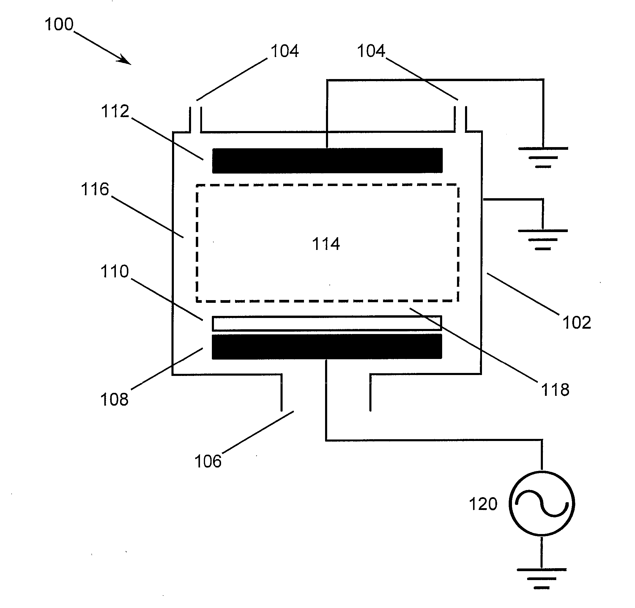
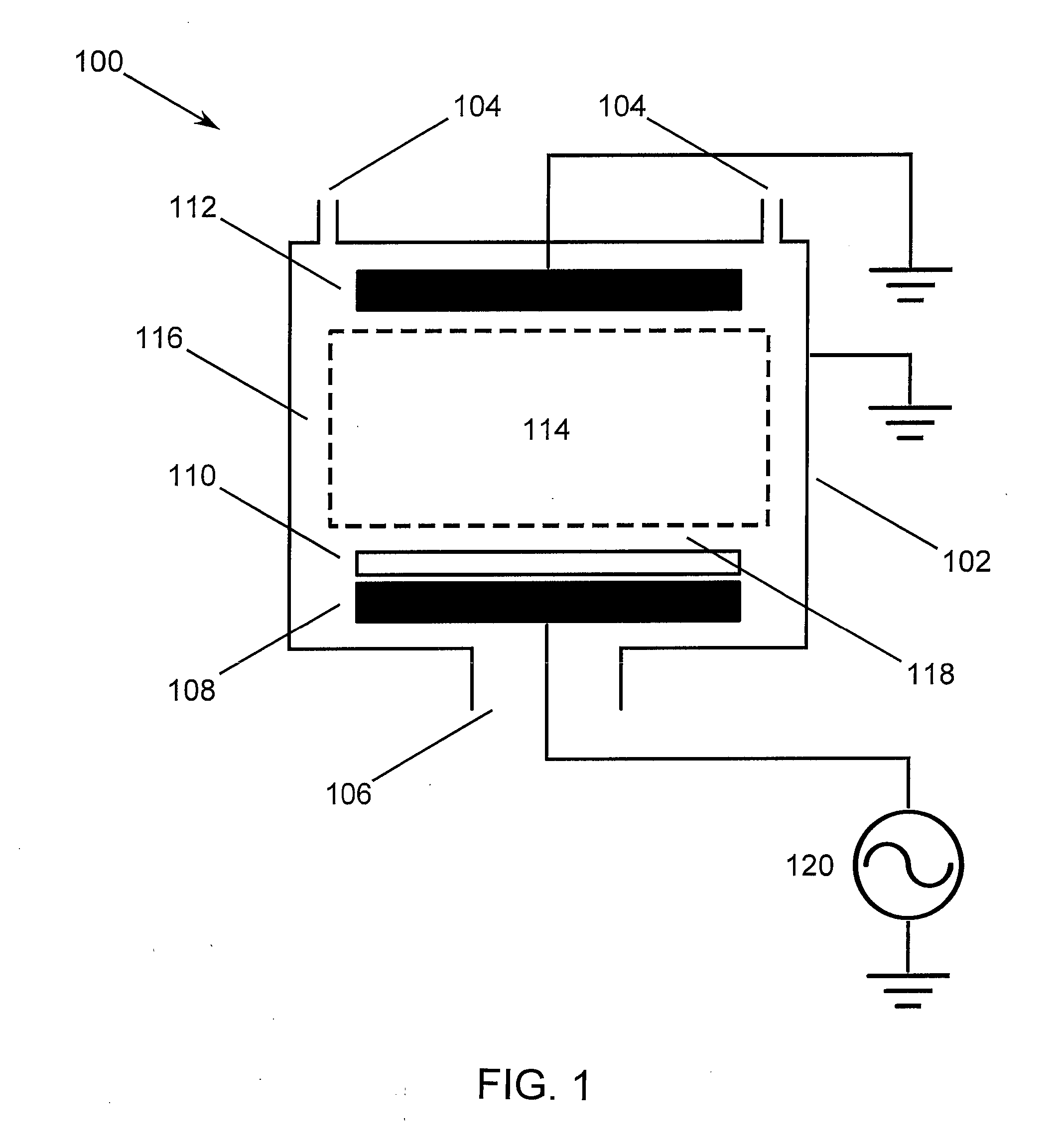
[0043]FIG. 1 shows a cross-sectional view of an idealized plasma operating apparatus with a capacity coupled plasma source. Other figures that show embodiments of plasma operating apparatuses are displayed in the same way. Embodiments of the invention using a variety of plasma sources will be detailed below to demonstrate the wide applicability of the invention. Components in these figures are denoted with a three digit number. Components which are identical use the same number through-out all of the figures. If components are similar or have the same function, then the last two digits are identical.

[0044]The plasma operating apparatus shown in FIG. 1 comprises a vacuum chamber wall 102, a gas inlet 104, a vacuum outlet 106, a powered electrode 108, a grounded electrode 112, and an RF voltage system 120. A plasma 114 is generated in the volume of the chamber in between the powered electrode 108 and the grounded electrode 112. This is a schematic embodiment of the invention. The inve...


PUM


Abstract

A method of establishing a DC bias in front of at least one electrode in a plasma operating apparatus by applying an RF voltage with at least two harmonic frequency components with a controlled relative phase between the components, where at least one of the higher frequency components is established as an even multiple of the lower frequency component.

Description

CROSS REFERENCE[0001]This application claims the benefit and priority of U.S. Provisional Application No. 61 / 038,263, which was filed on Mar. 20, 2008. U.S. Provisional Application No. 61 / 038,263 is incorporated herein by reference.TECHNICAL FIELD[0002]The present invention relates to the field of modification of surfaces and materials by exposure to low pressure plasmas and gases.BACKGROUND AND RELATED ART[0003]It is well known in the art that the flux and energy of ions is important in determining how a plasma treatment will affect a workpiece. There exist several different methods of adjusting the ion energy during plasma treatment, none of which are generally applicable.[0004]Coburn and Kay, J. Appl. Phys. 43(12):4965-4971 (1972) (cited as Coburn) describes a geometrically based Direct Current (DC) offset effect that depends upon a Radio Frequency (RF) voltage being applied across electrodes immersed in a plasma which have different surface areas. The method of Coburn is commonl...

Claims


Application Information

Patent Timeline
IPC IPC(8): H05H1/46
CPCH01J37/32009H01J37/32091H01J37/04H01J37/32165H01J37/32706H01J37/32146
Inventor HEIL, BRIAN GEORGECZARNETZKI, UWEBRINKMANN, RALF PETERMUSSENBROCK, THOMAS
Owner RUHR UNIV BOCHUM