Shock Wave Imaging System

a technology of shock wave and imaging system, which is applied in the field of shock wave imaging system, can solve the problems of high threshold energy requirements, high cost of shock wave unit, and inability to maneuver the patient table or shock wave unit,

Inactive Publication Date: 2008-02-07
AST
View PDF22 Cites 16 Cited by
  • Summary
  • Abstract
  • Description
  • Claims
  • Application Information

AI Technical Summary

Benefits of technology

[0015]Up to the present, shock wave units focused acoustical energy on one point or focal point hence the name focused shock waves. More recent patents DE10065450 or DE registered no. 102205017724-22 respectively publications as Eisenmenger UMB 2002, 28369-774 have described shock wave units with a larger therapy volume. In particular these new units can provide effective wave transmission over volumes far greater than a focal point. In fact the volumetric region of effective wave energy transmission can be considerably larger and the projected profile of this therapeutic volume can be established to a reasonable degree of certainty.
[0016]In today's clinical routine, all positioning and real time monitoring systems connected to shock wave units are based on a targeting on one point, which represents the point of highest energy.
[0017]The clinician is requested to position the volume to be treated (for example the stone) onto this point. To do so, expensive technology by means of a maneuverable patient table or shock wave unit must be utilized.
[0018]Amongst experts it is well accepted, that the marked focal point represents not necessarily the point of the maximal energy. The reasons are that this theoretical point is only established by measurements in water. It is considered the best possible approximation, because the propagation of the shock waves through the human body is conjugated by the changing tissues as skin, muscle, fat, etc.
[0019]Further aging processes of some types of shock wave units as well as the selected energy level always causes a shift of the point of highest energy from a predicted theoretical point. The shift caused by a burning of the electrode means the theoretical point is constantly shifting after repeated transmission pulses. Those described systematic deviations are being enlarged by any controlled or uncontrolled movements of the patients, e.g. respiration.
[0020]For the application of new shock wave units with larger therapy volume as described above, a positioning device on one point becomes practically useless and even in the old focal point shock wave units the emitted energy profile created a gradient form of therapeutic energy that could be very useful to the clinician treating a bone fracture wherein the control of the emitted energy profile is represented in a therapeutic volume which is invaluable in shock wave treatments.

Problems solved by technology

A primary factor in the reluctance to use ESWT was that the believed threshold energy requirements were so high that the surrounding tissue would hemorrhage, exhibited by hematomas and bleeding around the treated site.
To do so, expensive technology by means of a maneuverable patient table or shock wave unit must be utilized.

Method used


Image

  • Shock Wave Imaging System
  • Shock Wave Imaging System
  • Shock Wave Imaging System

Examples


Embodiment Construction

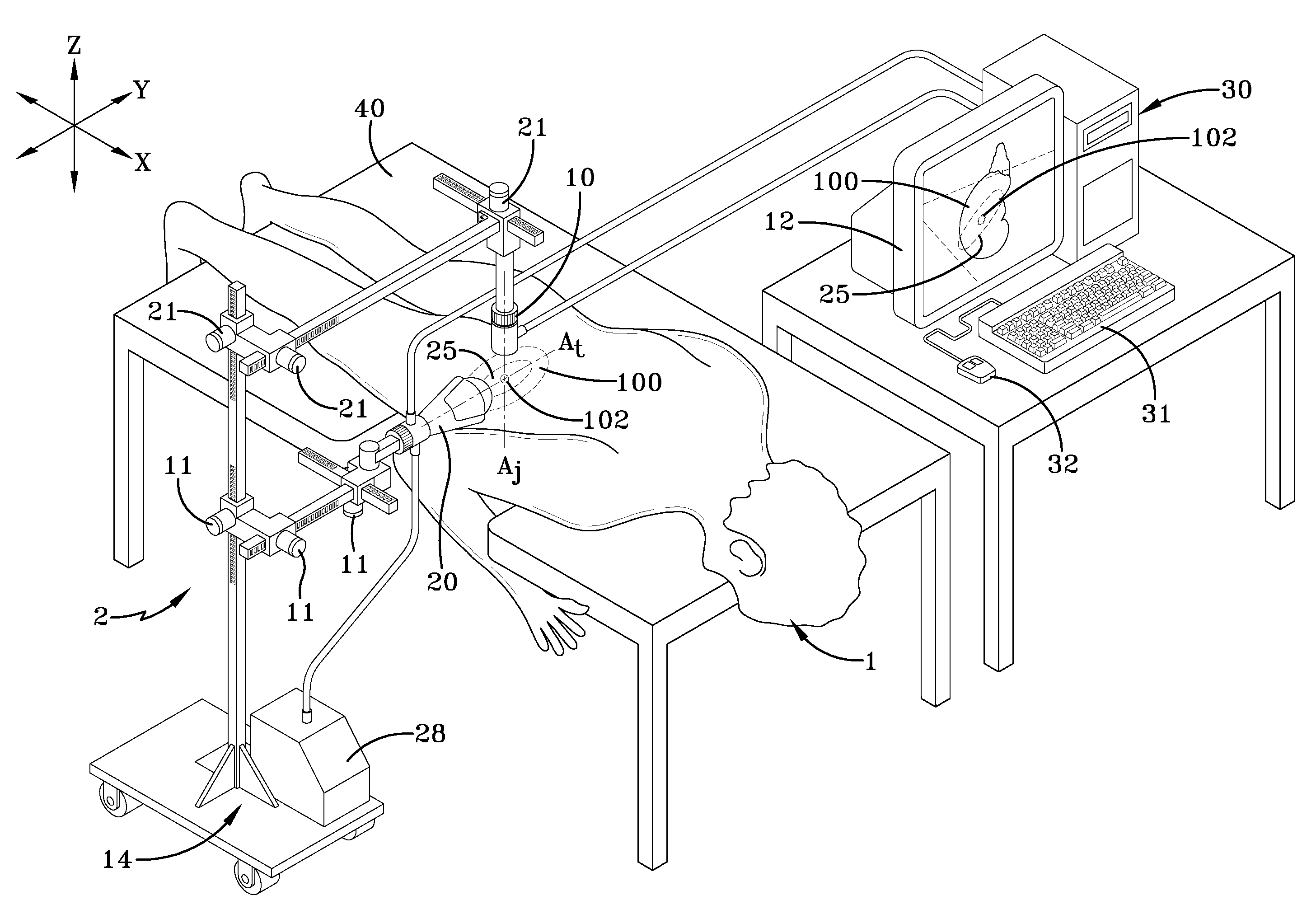
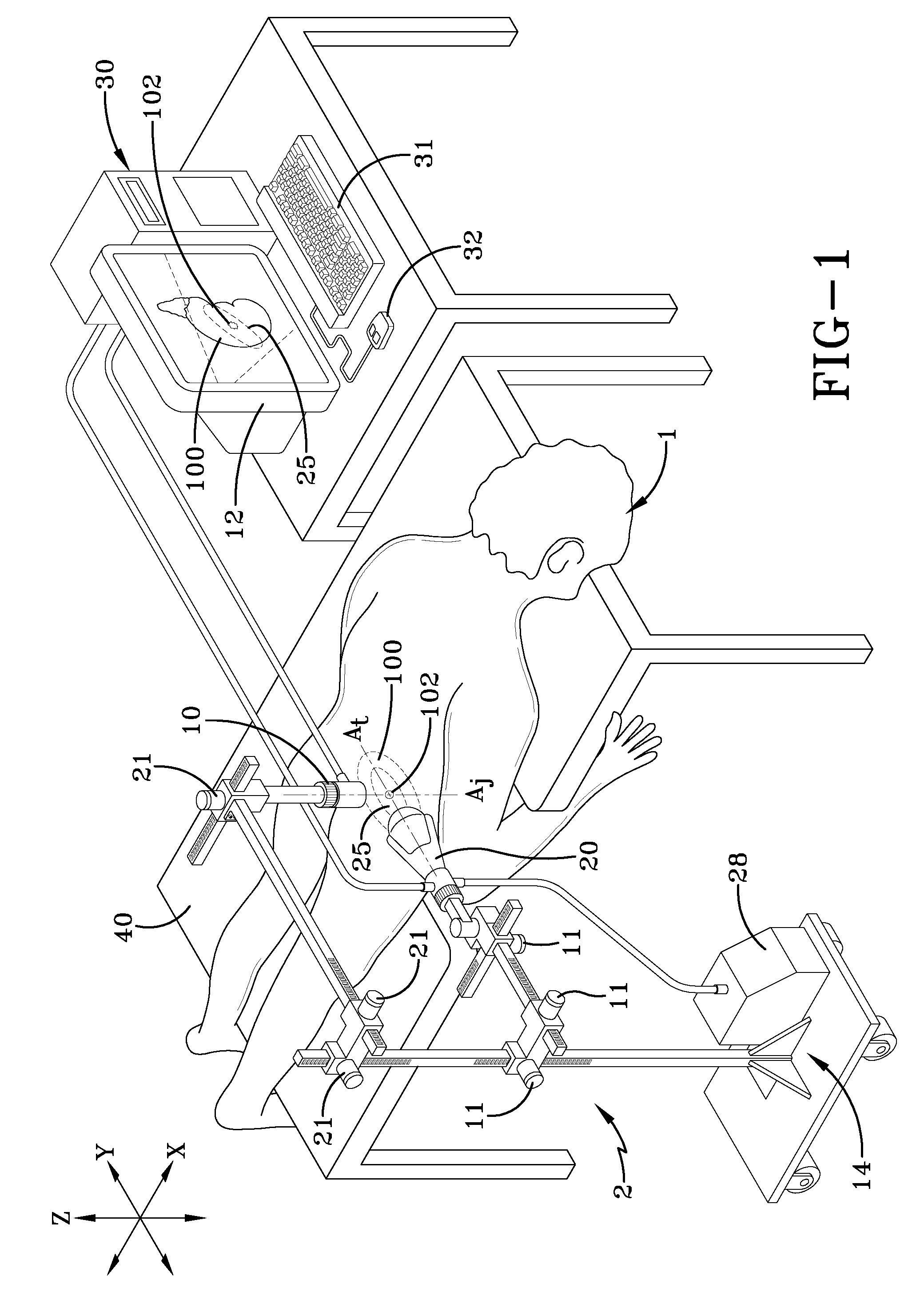
[0031]With reference to FIG. 1 a patient 1 is shown lying face down on an operating table 40. As shown an exemplary apparatus 2 is positioned to one side of the patient 1 about midway along the torso. An imaging device 10 is shown attached to a portable stand 14 and directed downwardly aiming in a region of the patient's kidney 100. The imaging device 10 has a projected axis or orientation Ai, Ai as illustrated being a vertical line. A treatment device 20 is shown oriented and has a treatment path 25 having a centerline directed along an axis At, as shown At intersects the axis Ai at location 102. Both devices are independently movable in the x,y,z axis either manually or an orienting / positioning system 18 by one or more servomotors 11, 21 such that the image device 10 can be oriented in any desired direction to achieve an optimal view of the treatment volume 100 on an image display monitor 12 while the treatment device 20 can have the path 25 directed in any desired orientation whi...


PUM


Abstract

A system or apparatus 2 for visually displaying and treating a treatment volume 100 located in a human or animal body 1 is disclosed wherein the treatment volume 100 is detected by a location finding imaging instrument 10 and displayed on a monitor 12 and a treatment instrument 20 is preferably oriented in response to the visual display to direct a treatment path 25 which is visually displayed superimposed onto the treatment volume 100.

Description

TECHNICAL FIELD[0001]This invention relates to a new and improved system to image and position a shock wave unit for optimal performance during therapeutic shock wave treatments.BACKGROUND OF THE INVENTION[0002]Electro-hydraulic shock wave systems have been used to disintegrate kidney and urethral stones by applying focused shock waves to the stone. A few hundred up to a few thousand shock waves may be required to break a stone within a mammal into small pieces of 3-4 mm diameter which are able to pass over a period of several weeks through the urethra and the bladder out of the patient's body.[0003]Devices using electro-hydraulic (U.S. Pat. No. 4,539,989), piezoceramic (U.S. Pat. No. 5,119,801) or electromagnetic (U.S. Pat. No. 5,174,280) shock wave or pressure pulse generating elements have been described.[0004]The patents used herein to illustrate the invention and, in particular, to provide additional details respecting the practice are incorporated herein by reference in their ...

Claims


Application Information

Patent Timeline
Patent Type & Authority Applications(United States)
IPC IPC(8): A61B6/00A61B8/00
CPCA61B17/2256A61B2019/5289A61B2019/5276A61B19/5225A61B90/37A61B2090/364A61B2090/378
Inventor SCHWARZE, WERNERSTEPHAN, HUGO
Owner AST
Why Eureka
Try Eureka