

Head mounted display and optical position adjustment method of the same
Active Publication Date: 2011-10-13
SONY CORP
View PDF4 Cites 150 Cited by
- Summary
- Abstract
- Description
- Claims
- Application Information
AI Technical Summary
Benefits of technology
[0024]In the methods of the present invention according to the first to fourth embodiments, the first image signal is controlled that is supplied to the image forming device making up at least one of the image display devices, thus controlling the position of the image displayed on the optical device making up at least one of the image display devices and thereby adjusting the mutual positions of the two images. This makes it possible to optically adjust the two image display devices for the right and left eyes, that is, adjust the optical positions of the two image display devices with ease to provide a desired image, for example, during manufacture of a binocular head mounted display. Further, the mutual optical positions of the two image display devices can be adjusted without using any special parts or mechanical adjustment, thus contributing to reduced number of manufacturing steps for the head mounted display and reduced manufacturing cost. Moreover, it is possible to readily respond to the change in mutual optical positions of the two image display devices over time, contributing to significantly reduced adjustment cost and adjustment time. That is, it is possible to electrically accommodate an assembly error of the head mounted display and the change in mutual optical positions of the two image display devices over time, thus providing the advantageous effects described above. Further, it is possible to instantly change the distance to the virtual image formed by the two optical devices according to the location and situation of use. Still further, the viewer can actively or passively change the distance to the virtual image, thus allowing for the viewer to view the virtual image at a comfortable position. Further, the head mounted display includes the image display devices, thus contributing to reduced weight and size of the head mounted display and providing significantly reduced discomfort while the head mounted display is worn.
described above. Further, it is possible to instantly change the distance to the virtual image formed by the two optical devices according to the location and situation of use. Still further, the viewer can actively or passively change the distance to the virtual image, thus allowing for the viewer to view the virtual image at a comfortable position. Further, the head mounted display includes the image display devices, thus contributing to reduced weight and size of the head mounted display and providing significantly reduced discomfort while the head mounted display is worn.
Problems solved by technology
This leads to discrepancy in preadjusted spatial distance to the virtual image, causing fatigue to the viewer during viewing.
However, such an adjustment is often difficult to achieve.
Method used
View moreImage
Smart ImageViewing Examples

Examples
example 2 (modification of example 1)
3. Example 2 (modification of example 1)
4. Example 3 (another modification of example 1)
example 4 (modification of example 3)
5. Example 4 (modification of example 3)
6. Example 5 (modification of examples 1 to 4)
example 6 (modification of example 5)
7. Example 6 (modification of example 5)
8. Example 7 (still another modification of example 1)
9. Example 8 (optical position adjustment method of the head mounted displays according to the second and fourth embodiments)
Login to View More PUM
 Abstract
Disclosed herein is an optical position adjustment method of a head mounted display, the head mounted display including (a) an eyeglass type frame worn on the head of a viewer, and (b) two image display devices for the right and left eyes attached to the frame, and each of the image display devices including (A) an image forming device, and (B) an optical device adapted to receive, guide and emit light emitted from the image forming device, wherein the optical position adjustment method includes the step of: controlling an image signal that is supplied to the image forming device making up at least one of the image display devices so as to control the position of the image displayed on the optical device making up at least one of the image display devices and adjust the mutual positions of the two images.
Description
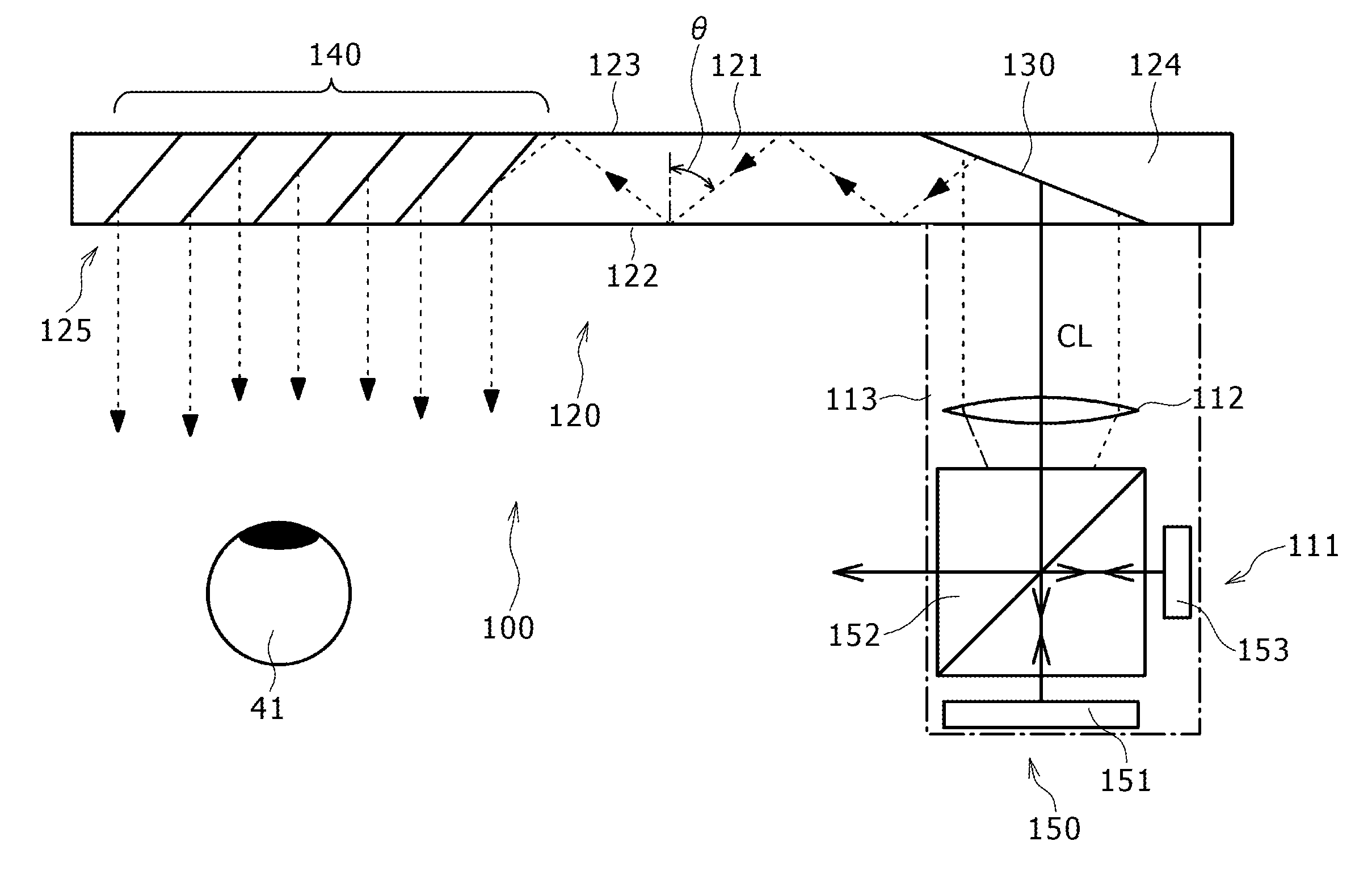
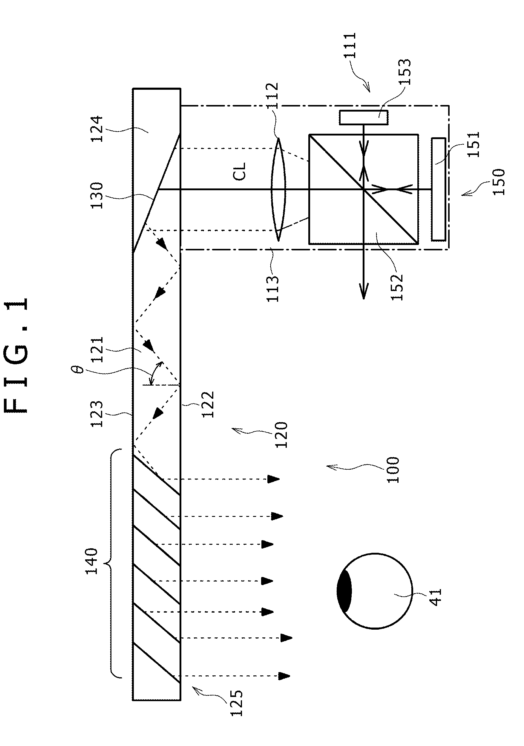
BACKGROUND OF THE INVENTION[0001]1. Field of the Invention[0002]The present invention relates to a head mounted display (HMD) and an optical position adjustment method of the head mounted display.[0003]2. Description of the Related Art[0004]A virtual image display device (image display device) is well known, for example, from Japanese Patent Laid-Open No. 2006-162767 that is designed to allow for the viewer to view a two-dimensional image, formed by an image forming device, as an enlarged virtual image by means of a virtual image optics.[0005]As illustrated in a conceptual diagram shown in FIG. 1, an image display device 100 includes an image forming device 111, collimating optics 112 and optical device (light guiding section) 120. The image forming device 111 includes a plurality of pixels arranged in a two-dimensional matrix. The collimating optics 112 shapes light, emitted from the pixels of the image forming device 111, into parallel beams. The optical device 120 receives light ...
Claims
Login to View More Application Information
Patent Timeline
 IPC IPC(8): G09G5/00
CPCG02B27/017G02B2027/0134G02B2027/0138G02B2027/0161H04N13/044H04N13/0497G06F3/012G06F3/1423G09G3/002G09G2356/00G09G2340/0464G09G2354/00G09G3/003G02B2027/014H04N13/344H04N13/398G02B27/0172G02B2027/0178G06T19/006G02B27/0103G02B2027/0109G02B2027/0174
InventorMIYAWAKI, TETSUYUKIMATSUMURA, IKUO
OwnerSONY CORP