Real-time ablation monitoring for desired lesion size

Inactive Publication Date: 2011-10-13
KONINKLIJKE PHILIPS ELECTRONICS NV
View PDF12 Cites 7 Cited by
  • Summary
  • Abstract
  • Description
  • Claims
  • Application Information

AI Technical Summary

Benefits of technology

[0034]In accordance with these, and other, aspects of the present invention, more control of dosing is afforded, to prevent under- or over-dosing of tissue. A convenie

Problems solved by technology

State-of-the-art MRI methods for monitoring HIFU ablation treatment base

Method used


Image

  • Real-time ablation monitoring for desired lesion size
  • Real-time ablation monitoring for desired lesion size
  • Real-time ablation monitoring for desired lesion size

Examples


Embodiment Construction

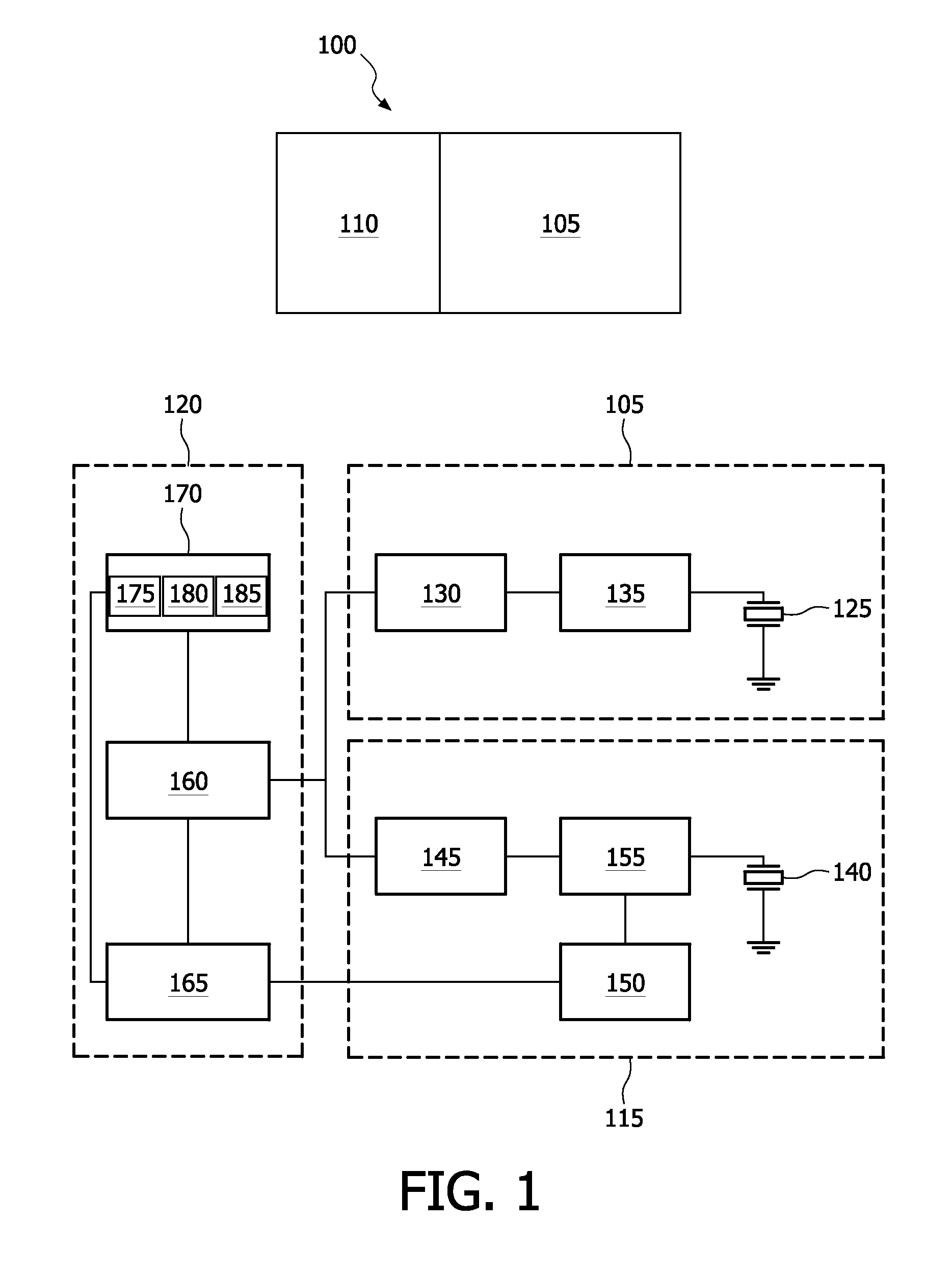
[0044]FIG. 1 depicts, by way of illustrative and non-limitative example, a functional diagram of an ablation apparatus 100, comprising, as shown in the upper part of FIG. 1, a therapy section 105 and an ablation control device 110.

[0045]As shown in the lower part, in more detail, the ablation control device 110 includes a monitoring section 115 and a control section 120.

[0046]The therapy section 105 has a high intensity focused ultrasound (HIFU) transducer 125, connected to an RF (radio frequency) amplifier 130 by means of a matching network 135.

[0047]The monitoring section 115 includes an imager transducer 140, connected to a pulser 145 and a receiver 150 by means of a transmit / receive (T / R) switch 155.

[0048]The control section 120 comprises an arbitrary waveform generator (AWG) and trigger 160, a digitizer 165, and a processor 170. The processor 170 includes a graphical user interface (GUI) 175, a master signal generator 180 and a motion controller 185 for controlling the position...


PUM


Abstract

An ablation control device (110) configured for halting, in real time, ablation of body tissue at a current ablation point to achieve a predetermined lesion size upon halting includes a control section (120) configured for registering, with a characteristic curve, one or more values and halting the ablation based on the registering. The value or values are obtained from monitoring (115), for the current ablation point, displacement caused by force applied to the body tissue. In one embodiment, halting is performed upon detecting, by the monitoring and after a peak value of the monitored displacement has occurred, an endpoint value of the monitored displacement. In another embodiment, the end-point value is determined prior to the detecting, and the determining is performed by the registering.

Description

FIELD OF THE INVENTION[0001]The present invention relates to ablation control, and more particularly to real-time control to achieve a predetermined lesion size.BACKGROUND OF THE INVENTION[0002]Tumor ablation therapy using high intensity focused ultrasound (HIFU) has been studied for many years and is just making its way into the United States market and clinical trials.[0003]A tumor, such as a cancer, can be medically treated by surgery and / or chemotherapy. Ablation therapy offers a less intrusive alternative. The ablation may be effected through various alternatives, such as by heating (e.g., radio frequency (RF) ablation, high intensity focused ultrasound (HIFU) ablation, microwave, and laser), freezing (e.g., cryogenic ablation) or chemical action.[0004]HIFU is non-intrusive, in that the thermal energy is applied from outside the body to focus on the tumor, but the energy is not concentrated enough to harm the patient's skin or more internal tissue before it concentrates on the ...

Claims


Application Information

Patent Timeline
IPC IPC(8): A61N7/02
CPCA61B8/08A61B18/18A61N7/02A61B2018/00904A61B2019/5276A61B18/20A61B2090/378
Inventor PETRUZZELLO, JOHNANAND, AJAYZHOU, SHIWEI
Owner KONINKLIJKE PHILIPS ELECTRONICS NV
Why Eureka
Try Eureka