Short Legged Bifurcated Stent Graft Distal Capture Element and Method

a stent and distal capture technology, applied in the field of stent grafts, stent graft delivery systems, and methods, can solve the problems of aneurysm development, blood entering the bloodstream, and aneurysms at risk of rupture, and achieve the effect of preventing the disengagement of the loop

Inactive Publication Date: 2011-10-13
MEDTRONIC VASCULAR INC
View PDF1 Cites 106 Cited by
  • Summary
  • Abstract
  • Description
  • Claims
  • Application Information

AI Technical Summary

Benefits of technology

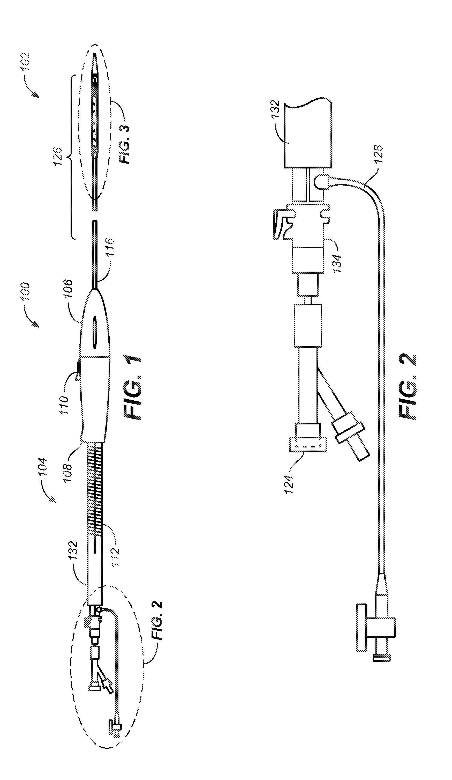
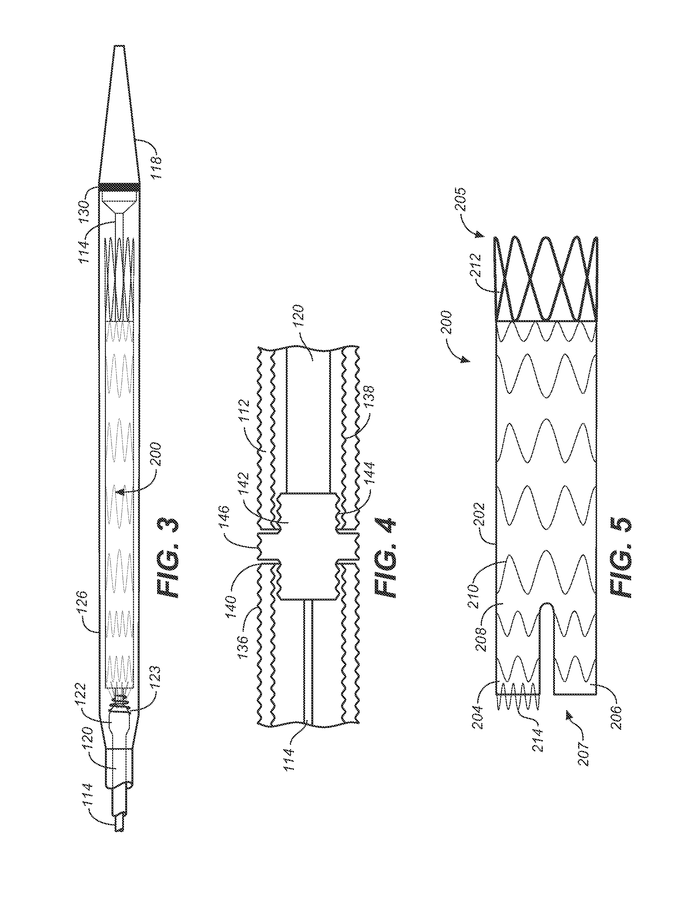
[0008]A bifurcated stent graft includes a plurality of loops formed from a serpentine shaped support at a distal end of one of its short legs. A delivery system includes a retention coil having a helically wound wire configured to pass through the loops and prevent disengagement of the loops from the delivery system without relative rotational movement between the retention coil and the loops. Rotating the coil in one direction causes the wire of the coil to capture the loops and hold the loops engaged with the delivery system. Rotating the coil in the opposition direction causes the wire of the coil to slip out of the loops to release the loops from the delivery system, allowing the short leg to which it is connected to expand and releases the short leg of the bifurcated stent graft section from the delivery system allowing the

Problems solved by technology

This arterial distention results in the development of an aneurysm, i.e., a bulging at the affected arterial segment.
An aneurysm is at risk of rupture resulting in extravasation of blood into, for example, the peritoneal cavity or into tissue surrounding the diseased artery.
Additionally, each particularly sized stent graft must be carefully constructed and handled, making it extremely costly to provide and ma

Method used


Image

  • Short Legged Bifurcated Stent Graft Distal Capture Element and Method
  • Short Legged Bifurcated Stent Graft Distal Capture Element and Method
  • Short Legged Bifurcated Stent Graft Distal Capture Element and Method

Examples


Embodiment Construction

[0032]With reference to the accompanying figures, wherein like components are labeled with like numerals throughout the figures, an illustrative delivery system and method of the delivering an endoluminal bifurcated stent graft section is disclosed, taught and suggested by the multiple embodiments.

[0033]Unless otherwise indicated, with respect to stent grafts described herein such as stent graft 200, the terms “distal” and “proximal” are used in the following description with respect to a position or direction relative to the heart. “Distal” and “distally” are positions distant from or in a direction away from the heart by way of blood flow path, and “proximal” and “proximally” are positions near or in a direction closest to the heart by way of blood flow path. With respect to delivery systems described herein, the terms “distal” and “proximal” are used in the following description with respect to a position or direction relative to the treating clinician. “Distal” and “distally” ar...


PUM


Abstract

A bifurcated stent graft section includes a plurality of loops formed from a serpentine support wire forming a stent at a distal end of one of the short legs of the bifurcated stent graft section. A delivery system includes a coil having a wire configured to pass through the loops and prevent disengagement of the loops from the delivery system without relative rotational movement between the coil and the loops. In a method for delivery the bifurcated stent graft section, the bifurcated stent graft section is advanced to the treatment site, a sheath is retracted to deploy the proximal end of the bifurcated stent graft section while the coil retains the distal end of one of the short legs of the bifurcated stent graft section. A second guidewire is threaded into the short leg of the bifurcated stent graft section which is been stabilized by being held by the coil of the delivery system. An extension leg graft is delivered over the second guidewire and deployed to be coupled to the other short leg of the bifurcated stent graft section while the coil retains the loops. The coil is rotated to release the loops and allow the bifurcated stent graft section to fully deploy. A second extension leg graft is delivered and coupled to the other leg of the bifurcated stent graft section to complete the construction of a bifurcated stent graft in situ.

Description

TECHNICAL FIELD[0001]This invention relates generally to stent grafts, stent graft delivery systems, and methods for delivering and deploying stent grafts to a desired location.BACKGROUND[0002]Endovascular aneurysmal exclusion is an evolving method for treating arterial aneurysmal disease. Aneurysmal disease causes the weakening and radial distention of a segment of an artery. This arterial distention results in the development of an aneurysm, i.e., a bulging at the affected arterial segment.[0003]An aneurysm is at risk of rupture resulting in extravasation of blood into, for example, the peritoneal cavity or into tissue surrounding the diseased artery. The goal of endovascular aneurysmal exclusion is to exclude from the interior of the aneurysm, i.e. aneurysmal sac, all blood flow, thereby reducing the risk of aneurysm rupture requiring invasive surgical intervention.[0004]One procedure developed to accomplish this goal entails providing an alternate conduit effectively internally ...

Claims


Application Information

Patent Timeline
IPC IPC(8): A61F2/84A61F2/82A61F2/06
CPCA61F2/07A61F2/954A61F2002/065A61F2002/075A61F2220/0033A61F2002/9517A61F2002/9665A61F2/89A61F2002/9505A61F2/9517
Inventor ACOSTA DE ACEVEDO, MARIA
Owner MEDTRONIC VASCULAR INC
Why Eureka
Try Eureka