Distributed system having a shared central database

Active Publication Date: 2011-10-13
CA TECH INC
View PDF23 Cites 19 Cited by
  • Summary
  • Abstract
  • Description
  • Claims
  • Application Information

AI Technical Summary

Benefits of technology

[0010]Requests for information from the central database may be made central database by each machine in the system. Since all machines in the system may have access to the information in the central database, there is no need for synchronization between machines as was required in the conventional system. Instabilities and inconsistencies between the various servers, which were found in the conventional system, can be eliminated with the system. Thus, the reliability of data in the system is greatly improved as compared to the convention system. Moreover, each of the backend databases in the system includes local schema information which references at least a portion of the central schema i

Problems solved by technology

However, synchronization and replication in this

Method used


Image

  • Distributed system having a shared central database
  • Distributed system having a shared central database
  • Distributed system having a shared central database

Examples


Example

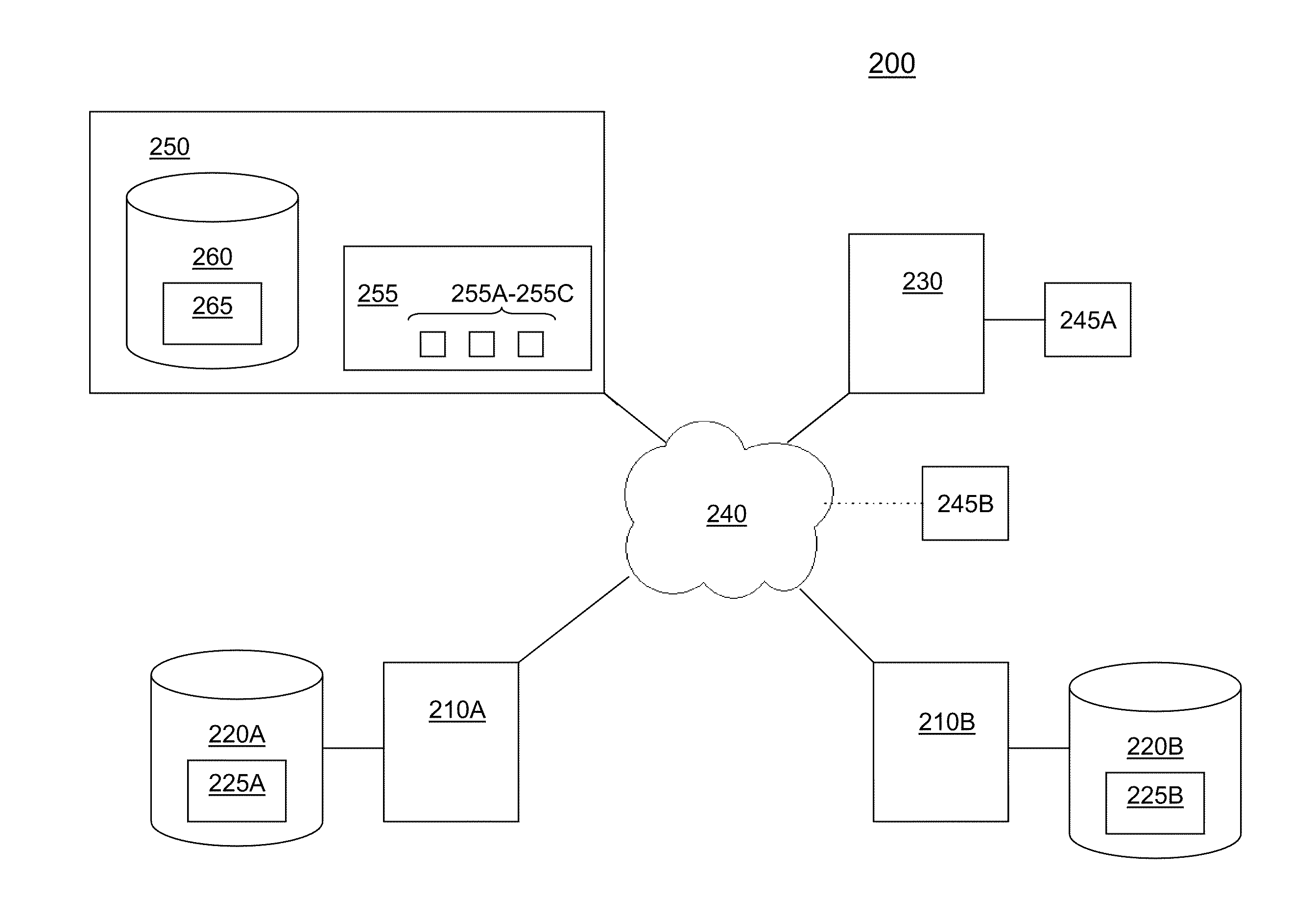
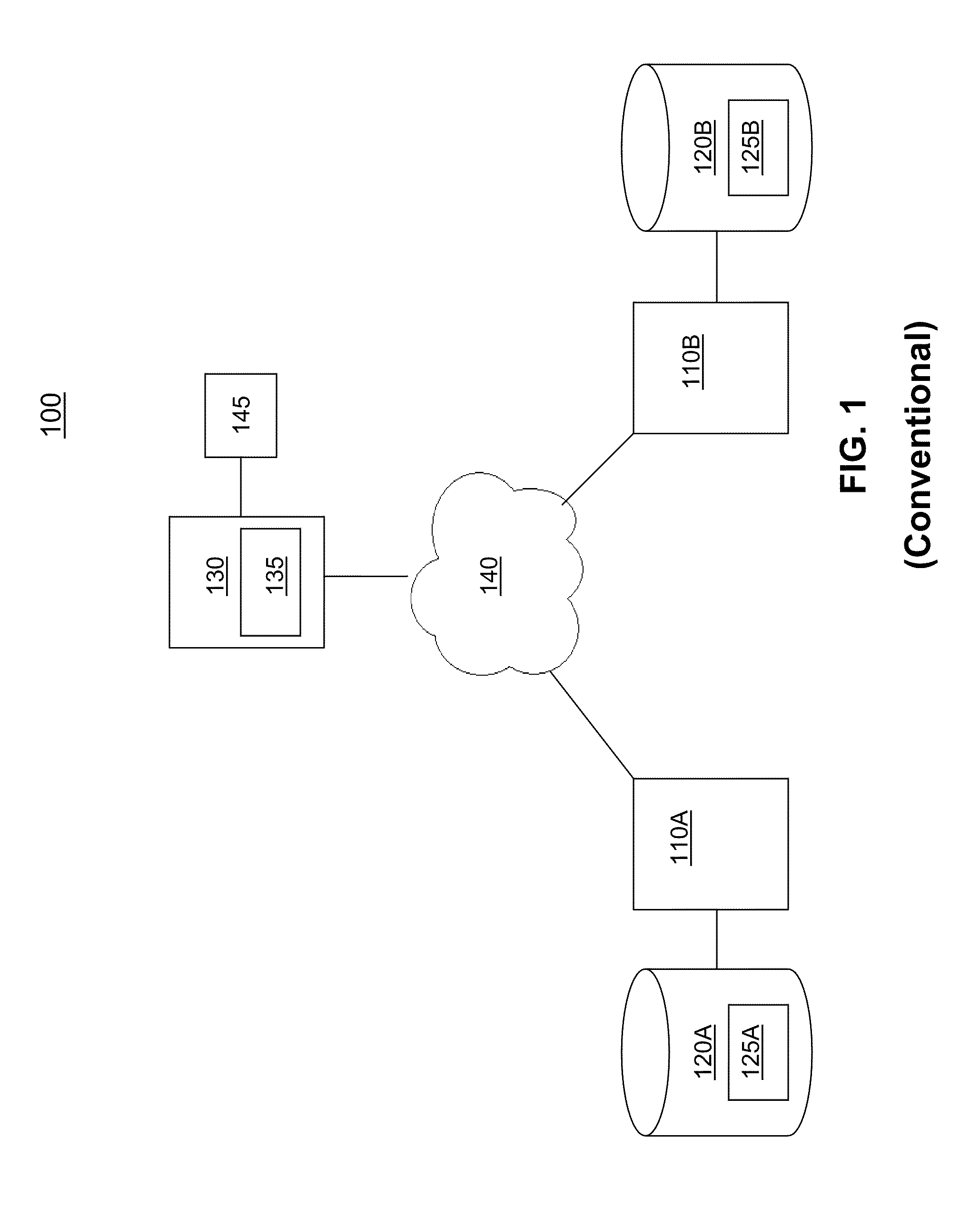
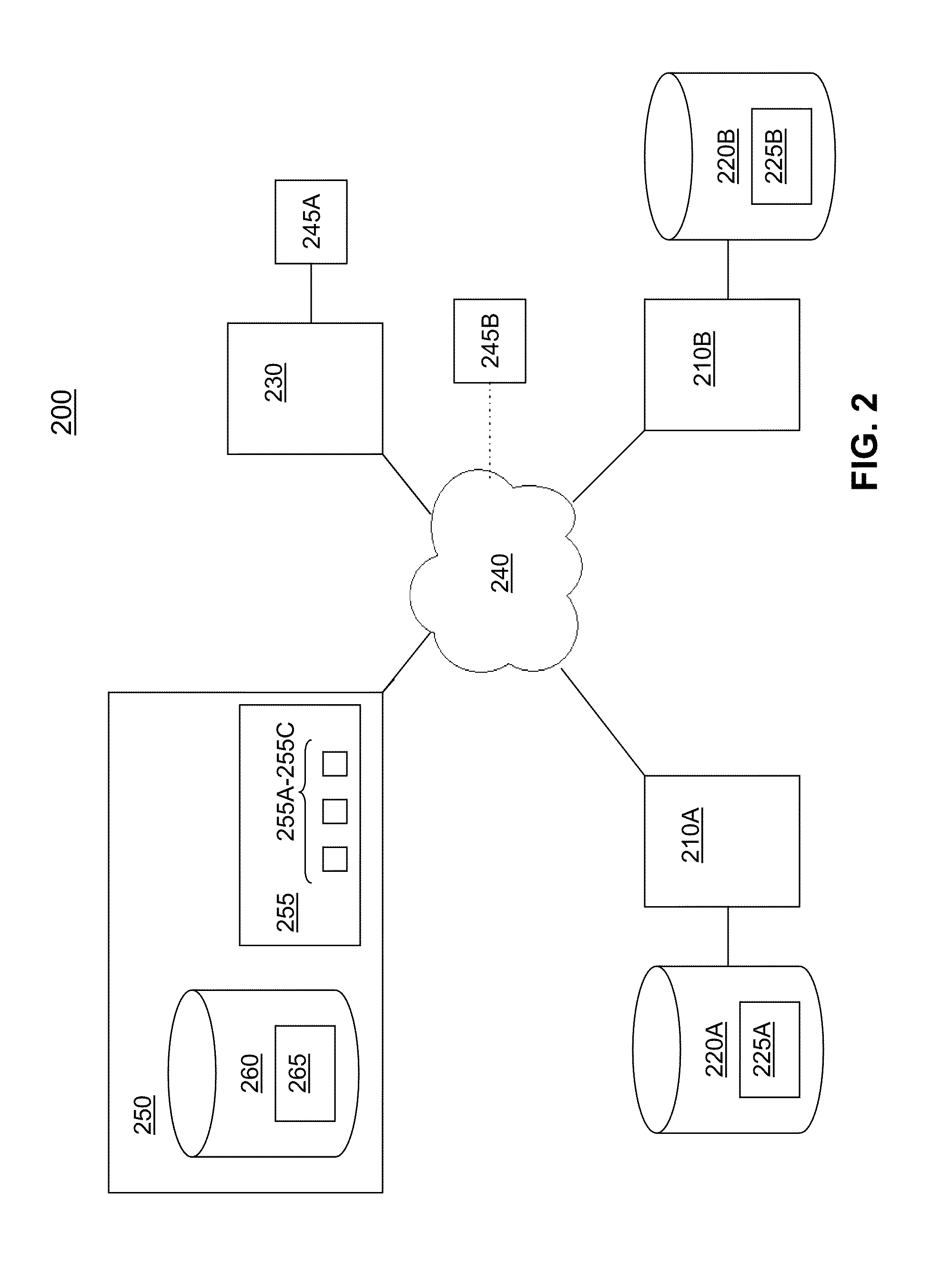
[0024]FIG. 2 shows an exemplary environment of distributed database system 200 having a shared central database in accordance with various implementations. In system 200, one or more backend servers 210 are configured to collect data. Collected data may include, but is not limited to, monitored data, and / or user-input data. Instead of storing collected data locally (as in the conventional system 100 shown in FIG. 1), each backend server 210 transmits data to a central database 250.

[0025]Data may be transmitted from one or more backend servers 210 or other machines, for instance, in real-time, on a batch basis, and / or at predetermined or scheduled times. In addition, management of data collection for each of the backend servers 210 may also be executed on central database 250 in system 200. This may also enable multiple backend servers 210 to collect and transmit data to the central database 250 using the same settings and / or according to the same schedule. Although, data collection ...


PUM


Abstract

A system for managing electronic information in a distributed system includes a shared central database for which a plurality of servers transmits data for storage. The shared central database is configured to store central schema information used for accessing the one or more data stores of the central database. Local databases each reference at least a portion of the central schema information for accessing the central database. Upon receiving a request for information, a local database directs the request to the central database based on the referenced schema information. The central database processes the request and transmits the data to the local database from which data was requested.

Description

FIELD OF THE INVENTION[0001]This disclosure generally relates to database management, and more specifically, to a distributed database system having a shared central database for central storage of data for all machines in the system.BACKGROUND ON THE INVENTION[0002]Distributed database systems that ensure the quality of services across an entire infrastructure enable users, among other things, to manage a diverse collection of devices, from numerous vendors, isolate the source of performance degradation, minimize recurring expenses, and provide detailed and executive level historical reporting.[0003]FIG. 1 shows a conventional architecture for a distributed database system 100. Conventional system 100 generally includes multiple backend servers 110 which are configured to collect and locally store data in one or more databases 120. The information which is collected by the backend servers 110A, 1108 and stored on database 120A, 120B may vary, for example.[0004]Schema information 12...

Claims


Application Information

Patent Timeline
IPC IPC(8): G06F17/30G06F7/00
CPCG06F17/30545G06F16/2471
Inventor LAUER, WILL C.SOARES, DAVID J.TRACY, BENJAMIN J.
Owner CA TECH INC
Why Eureka
Try Eureka