Display apparatus

Active Publication Date: 2007-07-05
PANASONIC LIQUID CRYSTAL DISPLAY CO LTD +1
View PDF3 Cites 61 Cited by
  • Summary
  • Abstract
  • Description
  • Claims
  • Application Information

AI Technical Summary

Benefits of technology

[0043] The display apparatus allows the data driver to be constructed as described in the above-mentioned means (6) through (8) so as to decrease a peak value of a momentary current generated in the data driver and improve reliability of the data driver and the display apparatus. The second latch circuit transfers display data in multiple blocks to the level shifter circuit more than once. The second latch circuit is constructed as described in means (7), for example. The display data is transferred as described in means (8), for example. This makes it possible to disperse a momentary current generated by driving the level shifter circuit and decrease a peak value. Accordingly, it is possible to improve the reliability of the data driver and the display apparatus.
[0044] The display apparatus according to the invention allows the scanning driver to be constructed as described in means (9) so as to cascade-connect multiple scanning drivers and output a scanning signal for black data in

Problems solved by technology

However, the inventors found that the conventional liquid crystal display apparatus causes the following problems.
A power supply voltage fluctuates due to the momentary current to degrade the reliability of the data driver and the display apparatus.
When multiple driver ICs are cascade-connected, there is a limitation on setti

Method used


Image

  • Display apparatus
  • Display apparatus
  • Display apparatus

Examples


Example

Embodiment 1

[0092]FIGS. 4 through 6 are schematic diagrams for illustrating the operational principle of the liquid crystal display apparatus according to embodiment 1 of the invention. FIG. 4 illustrates a method of dividing a drain line. FIG. 5 illustrates a method of outputting display data. FIG. 6 illustrates a method of setting a delay amount.

[0093] The liquid crystal display apparatus according to embodiment 1 aims at preventing a variation in times to write data to the TFT element of each pixel arranged in a direction along the extension of the gate line in liquid crystal display panel 1. As shown in FIG. 4, for example, the liquid crystal display apparatus is constructed to divide multiple drain lines DL provided for the liquid crystal display panel 1 into multiple blocks DBL1 through DBLn. When the data driver 2 outputs a display data signal (gradation voltage signal) to the drain lines DL, the data driver 2 shifts a timing for output to the blocks DBL1 through DBLn as sh...

Example

Embodiment 2

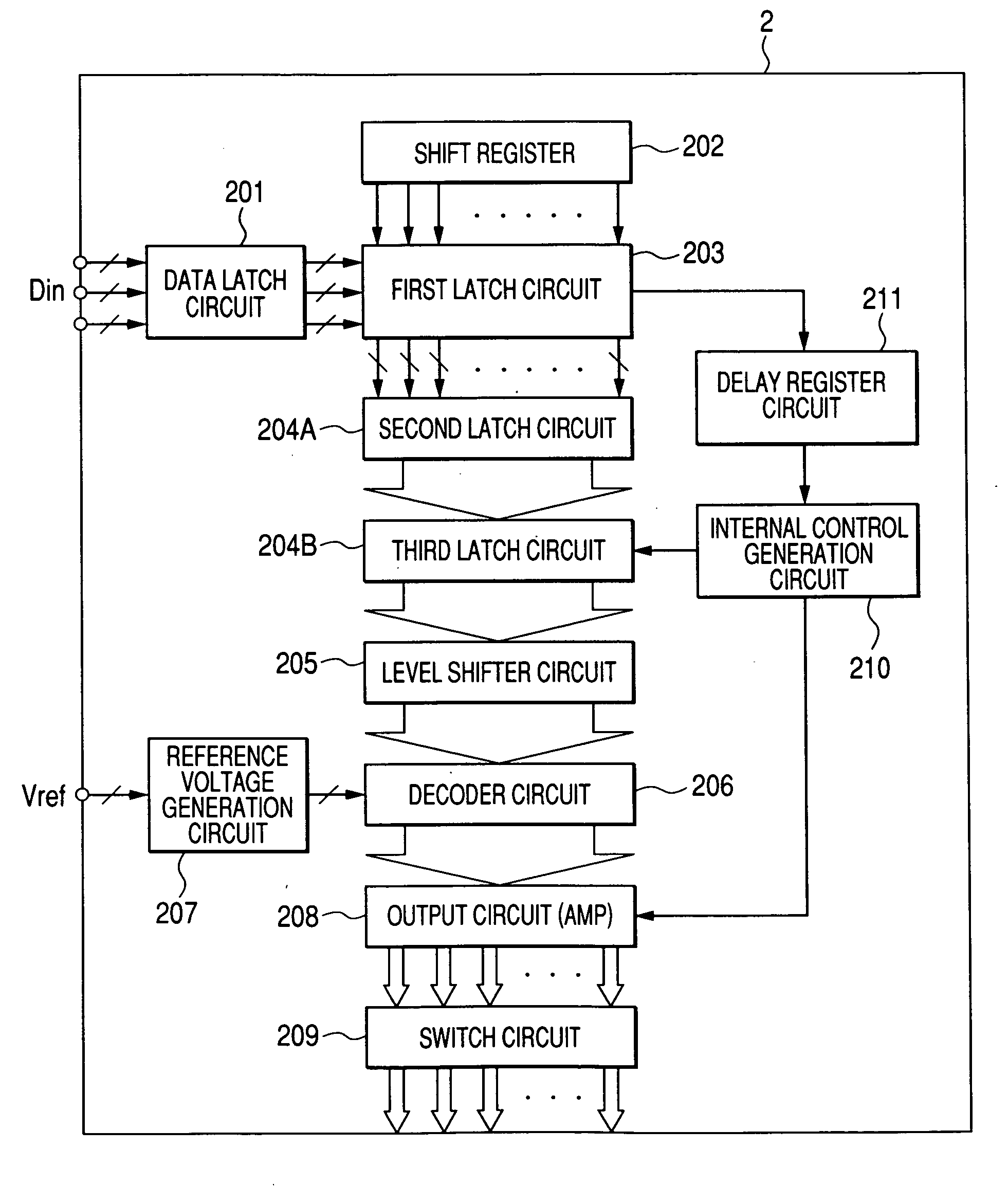
[0126]FIGS. 20 through 22 are schematic diagrams showing the overview construction of a display apparatus according to embodiment 2 of the invention. FIG. 20 is a block diagram showing a construction example of the data driver. FIGS. 21 and 22 are circuit block diagrams showing a construction example ranging from a horizontal synchronization signal delay circuit to a decoder circuit.

[0127] The liquid crystal display apparatus according to embodiment 2 aims at decreasing a peak value of a momentary current occurring in the data driver 2 and preventing reliability of the data driver 2 and the display apparatus from degrading. In such liquid crystal display apparatus, the data driver 2 is constructed as shown in FIG. 20. In the construction of the data driver 2 in FIG. 20, a conventional data driver is also constructed to include the data latch circuit 201, the shift register 202, the first latch circuit 203, the second latch circuit 204, the level shifter circuit 205, th...

Example

Embodiment 3

[0136]FIGS. 24 and 25 are schematic diagrams showing the overview construction of the display apparatus according to embodiment 3 of the invention. FIG. 24 is a block diagram showing a construction example of the scanning driver. FIG. 25 is a block diagram showing a construction example of a shift register circuit.

[0137] The liquid crystal display apparatus according to embodiment 3 inserts a black display at a constant interval when displaying an image (video). The liquid crystal display apparatus aims at cascade-connecting multiple scanning driver ICs and improving the flexibility of combining a gate line to output a scanning signal for display data with a gate line to output ascanningsignal forblackdatainsertion. In such liquid crystal display apparatus, the scanning driver 3 includes an input unit 301, a shift register unit 302, a level shifter circuit 303, a three-value selector circuit 304, an output buffer circuit 305, and an output unit 306 as shown in FIG. 24,...


PUM


Abstract

There is a need for decreasing a variation in times for writing to TFT elements for pixels in a direction along the extension of a gate line in a liquid crystal display apparatus. A display apparatus includes a display panel having multiple gate lines and multiple drain lines arranged in a matrix and a data driver for outputting a display data signal to each drain line. The data driver includes: an internal control signal generation circuit for generating an internal control signal for setting a timing to output a data signal to a drain line of each block on a block basis by dividing the plurality of drain lines into multiple blocks; and a register circuit for recording a setting for division of the block, a setting foradelay direction and a delay width of a timing to output the data signal, and a setting for rising and falling of an internal control signal.

Description

CLAIM OF PRIORITY [0001] The present application claims priority from Japanese Application JP2005-369758 filed on Dec. 22, 2005, the content of which is hereby incorporated by reference into this application. BACKGROUND OF THE INVENTION [0002] 1. Field of the Invention [0003] The present invention relates to a display apparatus. More specifically, the invention relates to a technology effectively applied to a liquid crystal display apparatus. [0004] 2. Description of Related Art [0005] Conventionally, display apparatuses include a liquid crystal display apparatus using a liquid crystal display panel. The liquid crystal display panel uses apair of substrates between which a liquid crystal material is sealed. The substrate is provided with multiple gate lines and drain lines in a matrix, for example. Two adjacent gate lines and two adjacent drain lines enclose an area, i.e., one pixel area. Each pixel area contains a TFT element or a pixel electrode. [0006] The liquid crystal display ...

Claims


Application Information

Patent Timeline
IPC IPC(8): G09G3/36
CPCG09G3/3677G09G3/3688G09G2310/027G09G2310/0286G09G5/001G09G2310/061G09G2310/08G09G3/20G09G2310/0289
Inventor TANAKA, YASUHIROISAMI, HIRONOBUIIDA, HARUHISAKIKUCHI, HIDENORIODE, YUKIHIDE
Owner PANASONIC LIQUID CRYSTAL DISPLAY CO LTD
Why Eureka
Try Eureka