Apparatus for reducing the size of the lower construction chamber of a laser sintering installation

a technology for laser sintering and construction chambers, which is applied in the direction of additive manufacturing processes, manufacturing tools, other domestic articles, etc., can solve the problems of increasing the cost per component situation owing to the additional powder needed, the volume of the construction chamber cannot be adapted variably to respective needs, and the quantity of powder required in laser sintering installations cannot be reduced. , to achieve the effect of reducing the size of the lower construction chamber, and reducing the lateral distan

Inactive Publication Date: 2011-10-20
EVONIK DEGUSSA GMBH
View PDF43 Cites 52 Cited by
  • Summary
  • Abstract
  • Description
  • Claims
  • Application Information

AI Technical Summary

Benefits of technology

[0004]additional or new side walls insertable into a lower construction chamber of an existing laser sintering installation, thus reducing a lateral distance between at least one set of opposing sidewalls and
[0005]a new vertically adjustable construction platform sized to consume the reduced lateral distance between the additional or new side walls when inserted into the lower construction chamber of the existing laser sintering installation.
[0010]In a further preferred embodiment, the present invention provides a method for reducing the size of a lower construction chamber of a laser sintering installation, comprising: inserting additional or new walls into an existing lower construction chamber of a laser sintering installation to reduce a lateral distance between at least one set of opposing side walls, and adjusting the lateral size of a vertically adjustable construction platform to correspond to the reduced lateral distance of the inserted side walls.

Problems solved by technology

However, a disadvantage of the available installations is that the volume of the construction chamber cannot be adapted variably to respective needs.
As a result, the quantity of powder required in laser sintering installations cannot be reduced, even during the construction of very small parts in a small quantity.
If the ratio of component volume to volume of the construction chamber worsens, the costs per component situation increase owing to the additional powder needed.

Method used


Image

  • Apparatus for reducing the size of the lower construction chamber of a laser sintering installation
  • Apparatus for reducing the size of the lower construction chamber of a laser sintering installation
  • Apparatus for reducing the size of the lower construction chamber of a laser sintering installation

Examples


Embodiment Construction

[0016]FIGS. 1 to 4 show the principle of the reduction in size of a construction chamber according to various embodiments of the invention. FIG. 5 shows a simplified schematic diagram of the laser sintering installation according to the first embodiment of the invention.

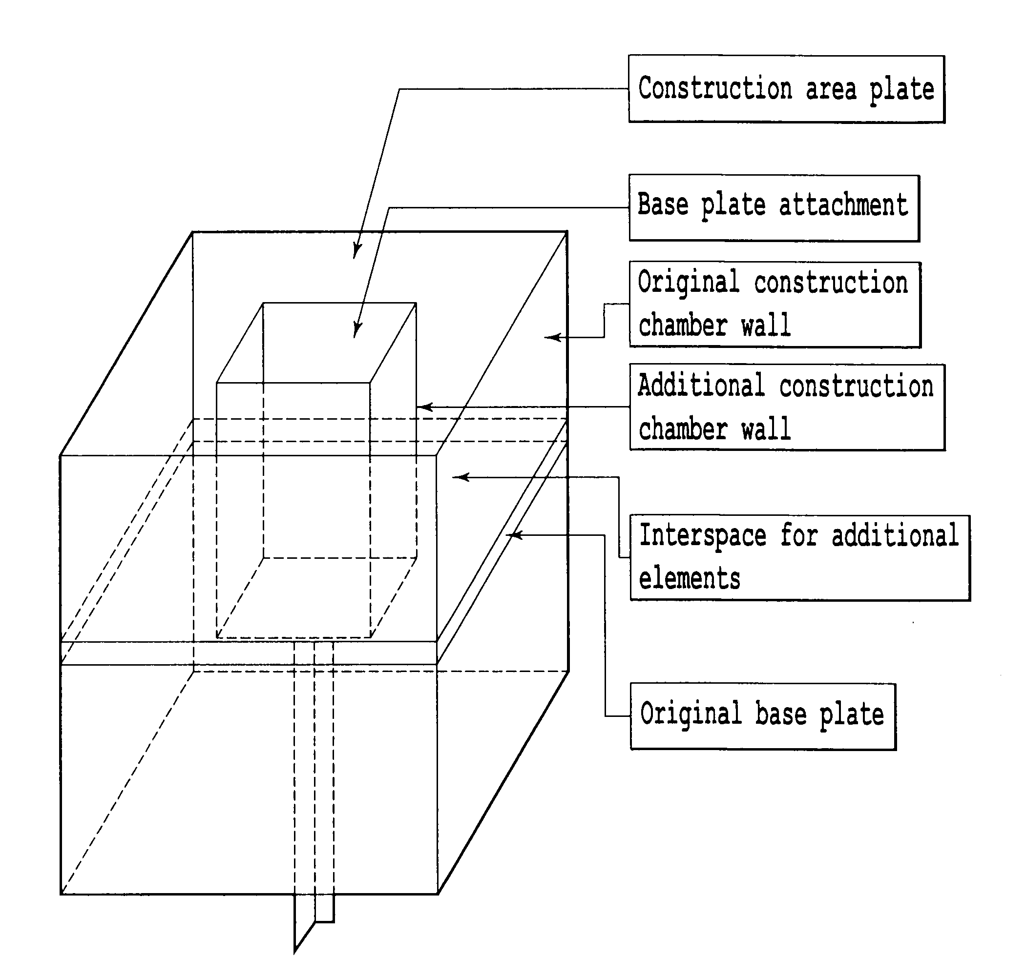
[0017]FIG. 1 is a simplified overall illustration of the present invention wherein additional or new side walls are inserted into a lower construction chamber of an existing laser sintering installation, thus providing additional or new side walls within the chamber and thereby reducing the lateral distance between at least one set of opposing sidewalls. A new vertically adjustable construction platform sized to consume the reduced lateral distance between the additional or new side walls when inserted into the lower construction chamber of the existing laser sintering installation is also placed in the chamber.

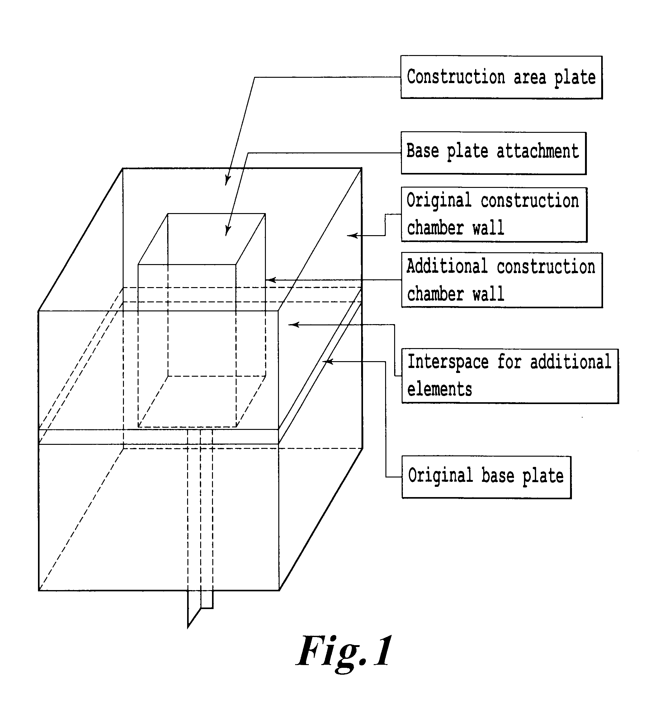
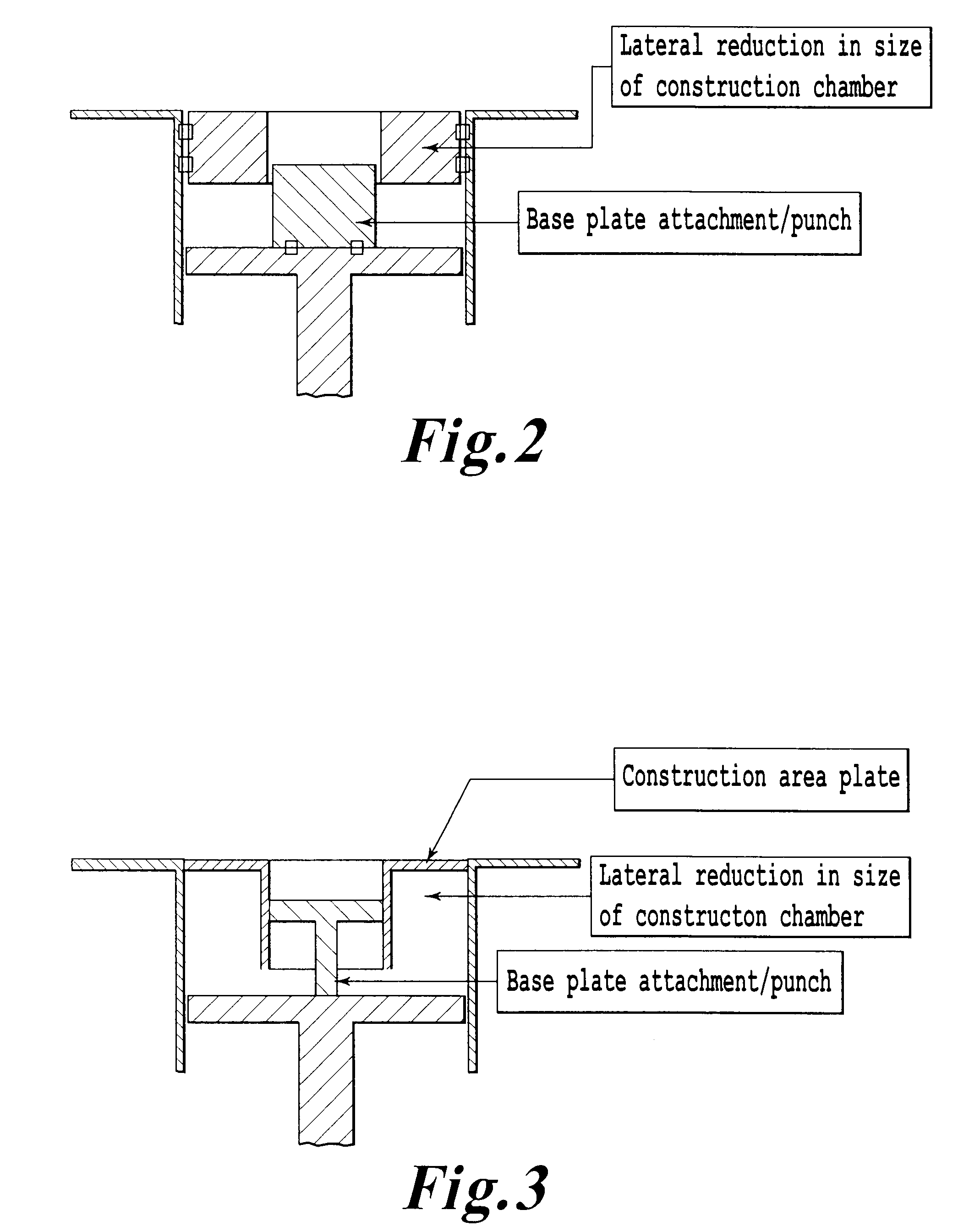
[0018]As shown in FIG. 2, the new construction platform may be a rigid base plate attachment placed on the ...


PUM

PropertyMeasurementUnit
sizeaaaaaaaaaa
lateral distanceaaaaaaaaaa
distanceaaaaaaaaaa

Abstract

An apparatus for the reduction in size of the lower construction chamber of a laser sintering installation is provided. Also provided is a method to reduce the size of the lower construction chamber of a laser sintering installation by insertion of the apparatus of the invention. The invention thereby provides for reduction in the demand for material for specific laser sintering requirements. In addition, a new degree of sintering process control is obtained when the apparatus contains heating or cooling units.

Description

CROSS REFERENCE TO RELATED APPLICATIONS[0001]This application claims priority to German Application No. 202010005162.2, filed Apr. 17, 2010, the disclosure of which is incorporated herein by reference in its entirety.BACKGROUND OF THE INVENTION[0002]Laser sintering installations are commercially available in various designs which differ, inter alia, in terms of the volume of the construction chamber. However, a disadvantage of the available installations is that the volume of the construction chamber cannot be adapted variably to respective needs. As a result, the quantity of powder required in laser sintering installations cannot be reduced, even during the construction of very small parts in a small quantity. If the ratio of component volume to volume of the construction chamber worsens, the costs per component situation increase owing to the additional powder needed.SUMMARY OF THE INVENTION[0003]It was therefore an object of the present invention to overcome the disadvantages of ...

Claims


Application Information

Patent Timeline
Patent Type & Authority Applications(United States)
IPC IPC(8): B23P19/04
CPCB29C67/0077B29C67/0085Y10T29/52Y10T29/49716B29C67/04B29C64/153B29C64/25
Inventor DIEKMANN, WOLFGANGGREBE, MAIKALTKEMPER, STEFAN
Owner EVONIK DEGUSSA GMBH
Why Eureka
Try Eureka