
Method for Operating a Bale Opener and Such a Bale Opener

a bale opener and bale technology, applied in mechanical equipment, packaging, transportation and packaging, etc., can solve the problems of high risk for the person operating the machine, cumbersome operation practice in subdividing the enclosure of the beam of light, and difficulty in staking out hazardous areas

Inactive Publication Date: 2017-10-19
MASCHINENFABRIK RIETER AG
View PDF2 Cites 1 Cited by
  • Summary
  • Abstract
  • Description
  • Claims
  • Application Information

AI Technical Summary

Benefits of technology

The invention is a method and device for opening bales of fiber with a laser scanner. The device has a unique design to improve safety and reliability. It uses a redundant design with different safety fields and monitoring regions to detect any failure or fault in real-time. The device can be used as a collision monitoring tool at the end of a group of bales. It also reduces the lateral distance between the stripping element and the bale opener. Additionally, the shape of the monitoring region can be adjusted to avoid masking out or avoiding objects that may interfere with the system. Overall, the invention provides a more reliable, cost-effective, and safe way to open bales of fiber.

Problems solved by technology

The working elements used in this process, for example, cutting rollers, are situated in positions that change constantly during operation due to the nature of the system and they cannot be covered, so they constitute a high risk for the person operating the machine, among other things.
Such a method of subdividing the enclosure of the beam of light has often proven to be cumbersome in operational practice.
When setting up a new bale recipient, the opposing safety enclosure is often broken through unintentionally, so that the machine is shut down.
When limited space is available, problems arise in staking out hazardous areas.
One disadvantage is that the sensors must be moved in order to create protective areas that can change in position.
In particular, the fact that the sensors and evaluation systems are mounted on the moving machines and / or machine parts, where they are exposed to substantial vibrations, which can lead to interference and dangerous failures of the safety system.
Another disadvantage is that the ultrasonic sensors that are used are expensive and in particular are very susceptible with respect to air influences such as air stratification, wind, etc.
Furthermore, the monitored area is small, i.e., not optimal, in particular with respect to its lateral coverage.

Method used


Image

  • Method for Operating a Bale Opener and Such a Bale Opener
  • Method for Operating a Bale Opener and Such a Bale Opener
  • Method for Operating a Bale Opener and Such a Bale Opener

Examples


Embodiment Construction

[0006]The invention is thus based on the object of creating a method for operating a bale opener and such a bale opener that avoids the disadvantages of the prior art.

[0007]The invention is also based on the object of creating a method for operating a bale opener and such a bale opener, which are less susceptible to interference, more reliable and less expensive than the methods and the systems offered in the prior art.

[0008]The invention is also based on the object of creating a method for operating a bale opener and such a bale opening, which can be used as collision monitoring in rotation of the stripping element.

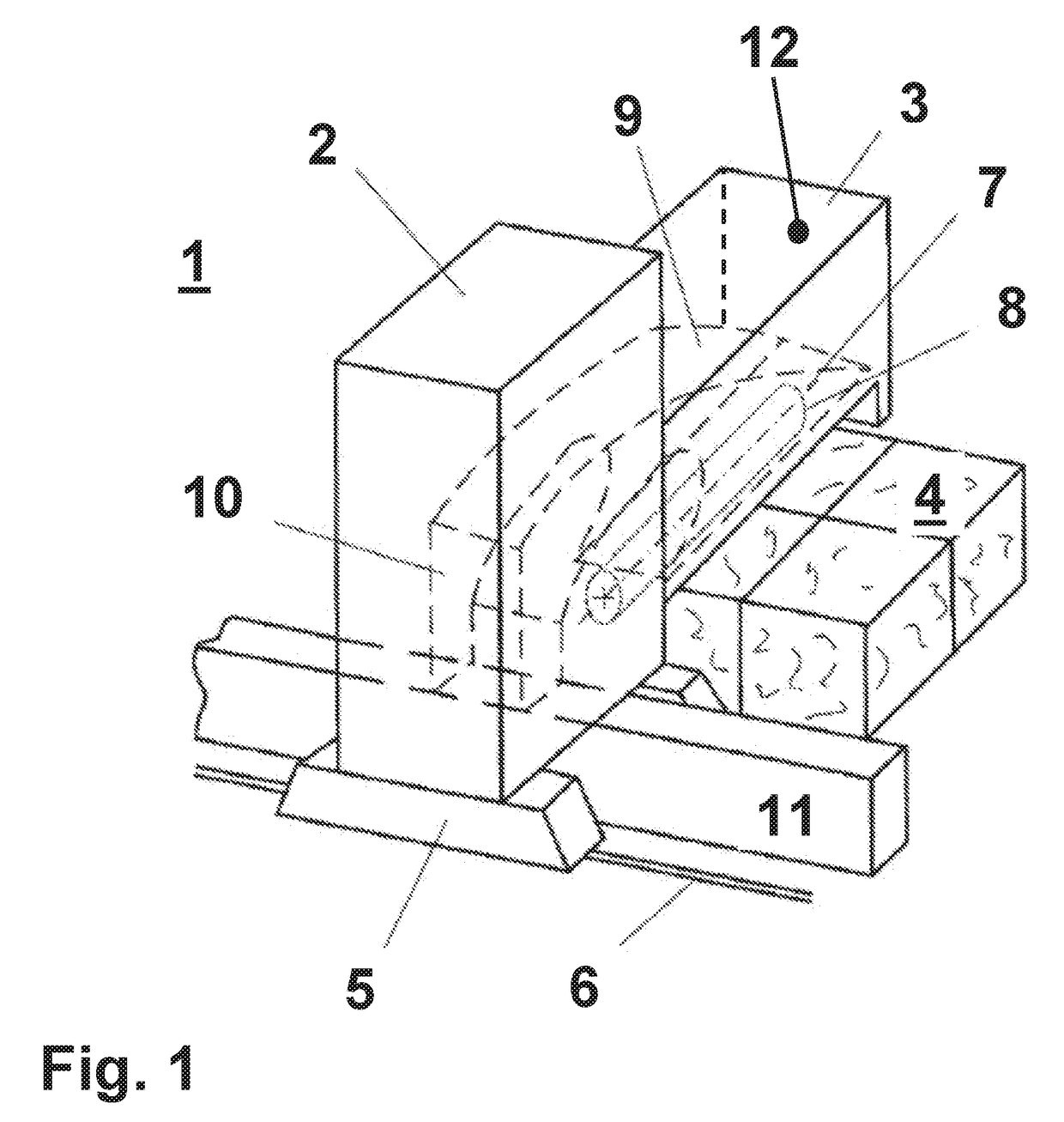
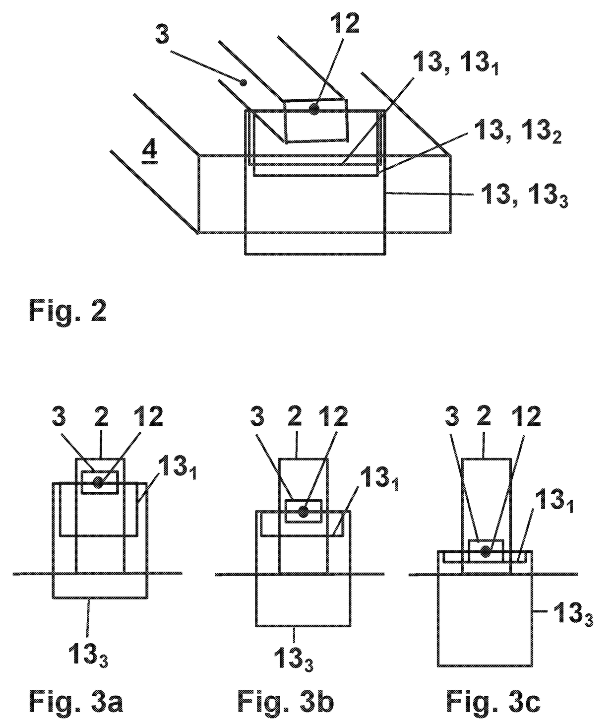
[0009]These objects are achieved by a method and a bale opener corresponding to the preamble of the independent claims, which are characterized in that the safety equipment comprises at least one two-dimensional laser scanner, on which at least one monitoring area that is adjustable and variable over time is monitored.

[0010]These objects are also achieved first by a comp...


PUM

PropertyMeasurementUnit
areaaaaaaaaaaa
depthaaaaaaaaaa
lateral distanceaaaaaaaaaa

Abstract

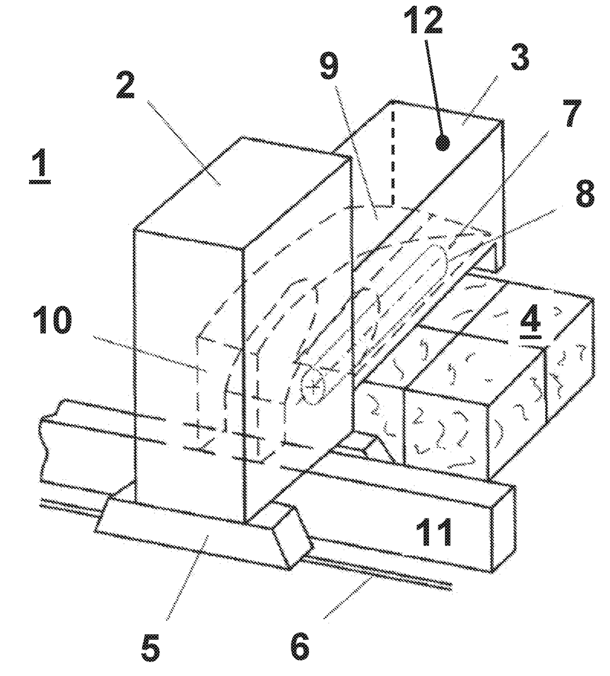
The invention relates to a method for operating a bale opener (1) having a stripping element (3) and a safety device for protection against penetration into a hazardous zone of the stripping element (3), said safety device consisting of sensory safety means, wherein a monitoring region (13, 131, 132, 133) at the front beneath the stripping element is detected and wherein the stripping element (3) is mounted on a stripping tower (2). According to the invention the safety device is at least one two-dimensional laser scanner (12), on which at least one monitoring region (13, 131, 132, 133), which is adjustable and variable over time, is monitored. The invention also relates to a corresponding bale opener (1).

Description

TECHNICAL FIELD[0001]The invention relates to a method for operating a bale opener having a stripping element and a safety device for protecting people from intrusion into a hazardous zone of the stripping element and a bale opener, in accordance with the preamble of the independent claims.PRIOR ART[0002]It is known that with machines in general and also with textile machines, the moving parts on the machine, in particular the drive devices, must be secured by a safety device to prevent anyone from approaching too closely. Inasmuch as the drive parts are arranged in a stationary mount with the movable parts, a fixedly mounted cover is sufficient in general. This may be designed so that the machine is automatically shut down when opening the cover.[0003]In practice, devices are present on textile machines, on so-called bale trimmers, to secure hazardous working elements. In the textile industry, in particular in spinning preparation, there are known machines for stripping fiber bales...

Claims


Application Information

Patent Timeline
Patent Type & Authority Applications(United States)
IPC IPC(8): D01G7/14D01G7/10D01G7/04
CPCD01G7/14D01G7/10D01G7/04B65B69/00D01G7/06D01G31/00F16P3/144
Inventor GSCHLIESSER, GERHARDSCHMID, ALEXANDER
Owner MASCHINENFABRIK RIETER AG
Learn More