
Electric Door Release Powered by Energy Harvester

a technology of energy harvester and electric door release, which is applied in the direction of wing knobs, keyhole guards, wing accessories, etc., can solve the problems of security failure risk, inconvenient operation of electric door release mechanism battery pack, and insufficient electrical capacitance, so as to achieve substantial electrical capacitance and continuous waste of energy

Active Publication Date: 2011-10-20
HANCHETT ENTRY SYST
View PDF3 Cites 65 Cited by
  • Summary
  • Abstract
  • Description
  • Claims
  • Application Information

AI Technical Summary

Benefits of technology

The present invention is about a system for powering an electric door release system using an energy harvester and a piezoelectric actuator. The system includes a voltage boost circuit and an actuator discharge circuit for recycling power back to the battery. The energy harvester can be a piezoelectric device or any other type of harvester for collecting waste energy. The system can also include a rechargeable battery or a compound Greinacher-type voltage douler circuit for continuous use. The energy generated by the harvester must be sufficient to keep the battery or capacitors fully charged. The technical effects of the invention are to provide a reliable and adaptable power source for electric door release systems, even in environments with variable or low frequency of local waste energy occurrences.

Problems solved by technology

Such a configuration has the disadvantage that the battery either must be kept charged in some fashion or must be replaced periodically, with risk of security failure if not timely replaced or if the recharging means fails.
Thus, where hard wiring of the mechanism from a remote power source is not possible, practical or desired, an undesirably large and expensive battery pack for operation of the electric door release mechanism is required.

Method used


Image

  • Electric Door Release Powered by Energy Harvester
  • Electric Door Release Powered by Energy Harvester
  • Electric Door Release Powered by Energy Harvester

Examples


Embodiment Construction

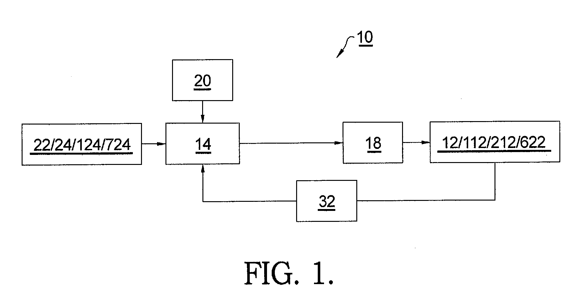
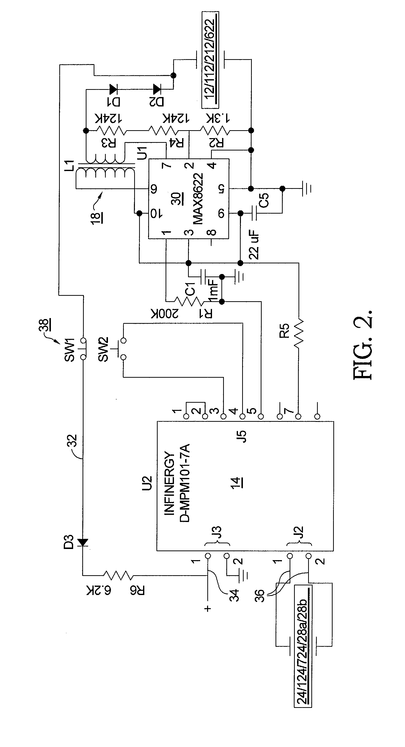
[0041]Referring to FIG. 1, a system 10 is shown for harvesting and utilizing waste energy to power an electrically operated door device such as a door release actuator in accordance with the present invention. System 10 comprises a device 12 such as a door release actuator 112; in one aspect of the invention, as described further herein, device 12 may be for example a low power consumption actuator, such as a piezoelectric actuator 212. When piezoelectric actuator 212 is used to release a door latch, system 10 may be powered by a power management module 14 that powers a voltage booster 18 for increasing voltage to a level sufficient to energize piezoelectric actuator 212. Power management module 14 is responsive to a door-release authorization signal 20 and receives power from any waste energy harvester 22, such as, for example, RF or solar cell harvesters, or other known sources of waste energy as described above, or alternately from a piezoelectric energy harvester 24 which may be...


PUM


Abstract

A system for operating an electric door release having an actuator powered by an energy harvester. The actuator may be a piezoelectric actuator and the harvester may be a piezo harvester. The system may further include a power module, a rechargeable battery and a voltage boost circuit disposed between the energy harvester and the actuator. When a piezoelectric actuator is used, a recycle actuator discharge circuit may be disposed between the piezoelectric actuator and the power module battery for recapturing a portion of the energy delivered to the piezoelectric actuator. The piezoelectric harvester may include an energy input portion whereby the piezo electric harvester is excited by the energy input portion. The energy input portion may include a circular or linear driving gear for exciting the piezoelectric harvester or a stepper motor generator, driven by movement of a door. The harvester may also be a stepper motor / generator.

Description

CROSS-REFERENCE TO RELATED APPLICATIONS[0001]This application claims the benefit of U.S. Patent Application No. 61 / 324,698, filed Apr. 15, 2010. U.S. Patent Application No. 61 / 324,698 is hereby incorporated by reference in its entirety.TECHNICAL FIELD[0002]The present invention relates to electrically operated devices associated with a door or closure, more particularly, to mechanisms for electrically locking or unlocking a door in a frame; further, to such mechanisms wherein the power to operate the electrical mechanism is collected and provided by an energy harvester; and most particularly, to an electric door release mechanism which may be actuated by a piezoelectric actuator powered by an energy harvester such as, for example, a piezoelectric energy harvester.BACKGROUND OF THE INVENTION[0003]So-called “energy harvesters” and “energy harvesting” refer generally to apparatus and methods for collecting and storing energy present in the environment, such as heat or solar energy, RF ...

Claims


Application Information

Patent Timeline
Patent Type & Authority Applications(United States)
IPC IPC(8): E05B47/00E05B3/00E05B15/02H02K7/18E05B65/06
CPCE05B1/0007E05B13/108E05B47/0011E05B47/0673E05B2047/0062E05D11/00E05Y2900/132E05Y2400/616H02N2/18E05Y2201/246E05Y2201/43E05Y2800/67E05Y2400/61Y10T292/57Y10T292/705Y10T70/5199E05D7/00E06B7/28H02N2/183
Inventor WEBB, MICHAEL A.CHRISTIANSEN, CHARLESHANCHETT, JR., LELAND J.SULLIVAN, SCOTT
Owner HANCHETT ENTRY SYST
Learn More